0
\$\begingroup\$

I need to measure bus voltage and guarantee my ADC is protected in a compact way. I came up with the following measurement circuit a long time ago in another design.
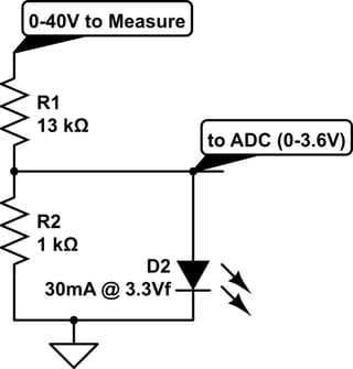
schematic

simulate this circuit – Schematic created using CircuitLab

The LED characteristics: starts conducting at 2.7V with 30mA at 3.3V.

The bus being measured has motors on it and may rise above 40V if/when they are generating. The goal is to prevent ADC damage from unforeseen overvoltage. Typically the bus will be at 24V or 36V nominal. The system would take action to prevent excessive overvoltage over 40V.

I had tried a zener in place of the LED and it did not work. I don't remember why and I would not be surprised if, at the time, I either did not drop the divider resistance down enough to supply enough breakdown current, or even stuffed the part in backwards. I'm using 0402 1/10W resistors. Probably I was concerned with them dissipating the 5mA needed for zener breakdown. The 3mA for the LED circuit was a bit closer to what they are rated for.

I have severe space constraints. Is there a better way to do this?

\$\endgroup\$
8
  • \$\begingroup\$ with no LED and R ratio 40V reduces to 2.85V with no load. hmm what is your Vin min and Iout max,spec? \$\endgroup\$
    – D.A.S.
    Commented May 28, 2017 at 23:51
  • \$\begingroup\$ SH ADC with a recommended source impedance of 200 Ohm. \$\endgroup\$
    – hauptmech
    Commented May 29, 2017 at 1:16
  • \$\begingroup\$ are U measuring 0 to 40V and just want a zener for unforeseen overvoltage? because that must be clearly stated because 30mA implies an input of 30mA * 13k= 390Vdc so what is your Abs Max V for Vin? Thus is usually done by a Schottky diode pair clamp to each rail in one or pref. 2 stages like all CMOS. \$\endgroup\$
    – D.A.S.
    Commented May 29, 2017 at 2:37
  • \$\begingroup\$ The white LED can be modelled as Vth=2.8V and Vf= Vth+If/Pd for ESR~1/Pd for package rating =Pd not actual power used. Same can be done for Sch, Diodes, TVs \$\endgroup\$
    – D.A.S.
    Commented May 29, 2017 at 2:43
  • \$\begingroup\$ Sorry for the confusion. 30mA is the character of the LED in the circuit. Expected Abs Max V would be not too far over 40. The circuit did it's job in the previous design, but I'm looking for a better way. \$\endgroup\$
    – hauptmech
    Commented May 29, 2017 at 9:20

3 Answers 3

2
\$\begingroup\$

As I said in a comment to the other answer - a low voltage zener like 3.3 or 3.6V would start to conduct much before it's nominal zener voltage. It may conduct small current like 100-200uA at something about 2V and this way it will seriously distort your divider's output. These zeners need current of at least 30-40mA to get their voltage near their tollerance range.

A low power LED has better characteristics than a low voltage zenner, but I think it will also add some non-linearity to your resistor divider.

Check your ADC's specifications. Check what is the highest input impedance you can afford for your sampling speed. In such cases I prefer to raise the impedance of the divider so its current to be about 200-400uA and place no zener. This 400uA current on bus overvoltage can be carried out by MCU's ESD diode (not recommended!) or by an external small signal schottky diode (for example BAT46W) to Vcc's bulk electrolyte capacitor. This diode will have a reverse current of less than 1uA at 25C temp. and less than 5uA at 60C temp. so it wouldn't mess the divider voltage much. You could also find a diode with lower leakage current.

Also a capacitor of at least 20pF would be good to have near the pin.

\$\endgroup\$
2
\$\begingroup\$

Elaborating on Todor Simeonov's answer:

Your SAR ADC charges its input cap when sampling. Check its datasheet value, it is usually pretty small.

Place a capacitor which is at least (2^NBits) times higher across the input. Now, when sampling occurs, the ADC sampling cap is charged from this filter cap, and the values ratio ensures voltage does not drop more than 1 LSB.

Now, you can use very high resistor divider values, in the MegOhms, without problems! This neatly solves your input protection issues, all for the price of a tiny SMD cap. Use C0G, as X7R is vibration sensitive.

Take care about your sample rate, though. Each sampling consumes an amount of charge from the filter cap, and you want it to settle back to its normal value before sampling again. High resistor values will increase this settling time. So don't sample more often than your RC network's settling time constant.

If you are monitoring battery voltage, surely you do not need to sample it 100000 times per second...

\$\endgroup\$
0
0
\$\begingroup\$

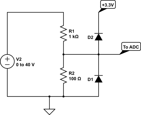
The normal way to do this is with diode clamps to the supply voltage:

schematic

simulate this circuit – Schematic created using CircuitLab

This will clamp the voltage to within a diode drop of the voltage rails, and the resistor divider will limit the current. You can use a shottky diode for better clamping. Note the reverse leakage current of the diodes. It will flow through the voltage divider and create an offset. There is a tradeoff between clamping voltage and reverse leakage.

This is an extra diode compared to your version, but you can buy SOT packages with 2 diodes wired up like this for exactly this purpose, so it can be quite small. The dual diode package will also have better leakage current matching especially over temperature than two discrete diodes.

This circuit also already exists on every input pin of most ICs. External diodes will simply handle more current safely. Depending on your voltage divider, you may not need any protection diodes at all.

\$\endgroup\$

Your Answer

By clicking “Post Your Answer”, you agree to our terms of service and acknowledge you have read our privacy policy.

Not the answer you're looking for? Browse other questions tagged or ask your own question.