I am developing a AC current measurement device based on Current transformer.
I was taking a look to many questions related with this subject but in this case I would need some help
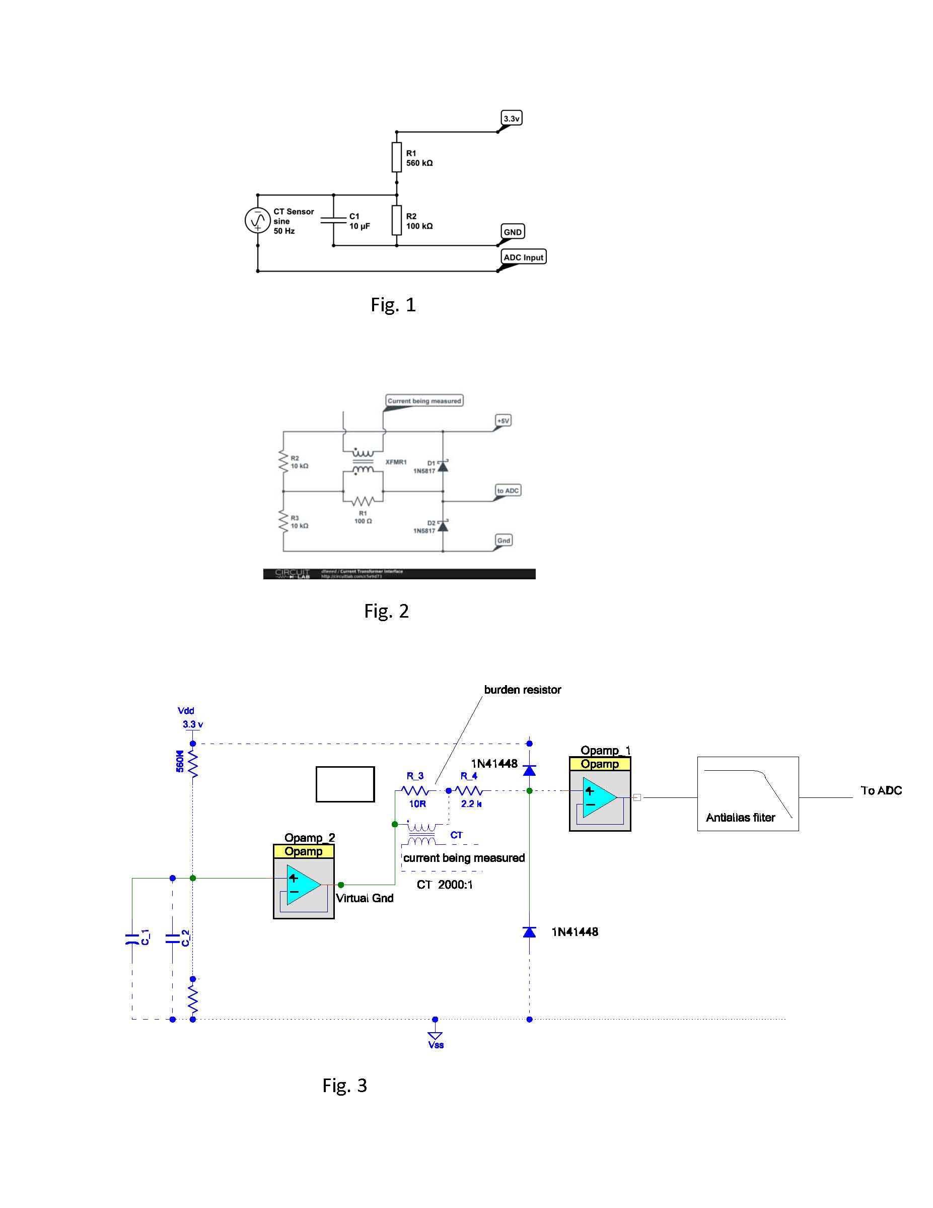
regarding the microcontroller chip input circuitry. As you can see from the attached schematics Fig.1 and fig. 2 were taken from other questions, so these ones inspired me partially to implement the input protection for my circuit. As reference I am using a SOC chip MCU, precisely PSoC 5LP from Cypress.
As CT, I am using 2000:1- 30 A/15 ma - R burden :10 ohm.
The following link is the data sheet for the CT.
(https://dlnmh9ip6v2uc.cloudfront.net/datasheets/Sensors/Current/ECS1030-L72-SPEC.pdf )
In fig 3 ( dash lines are a issue I have with the editor), I'm showing a resistor divider 560k / 560k and a couple of capacitors for decoupling the central point of the voltage divider.
My question is regarding the value that should have the resistor R_4 that limit the current after the burden resistor_3.
Looking at the PSoC 5LP data sheet regarding the absolute maximum ratings for a input pin, in this case is the OP-AmP_1 input, the min current should be -30 ma and max should be 41 ma. The maximum input voltage for the pin should be 3.3 V + 0.5 V. I'm using one of two option 3.3v or 5V as VDD. I would like some hint about how calculate that resistor value.
My other question is if 1N4148 can protect the input , I am not sure . Should I use Shottky diodes?
Thank you very much for some help.

