1
\$\begingroup\$

I am switching an IRFP250M with a square wave. Its output should be a sqquare wave too, but this is what i'm getting:

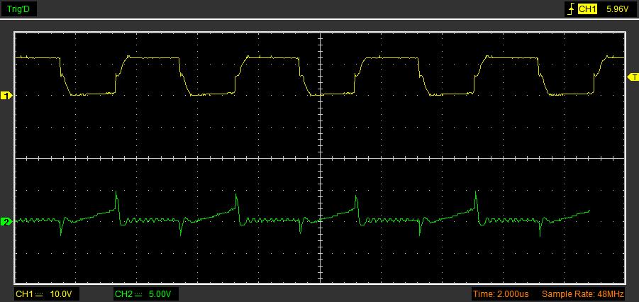
Measurements at 255kHz: oscilloscope output

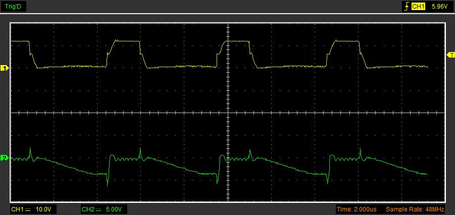
Measurements at 200kHz: oscilloscope output

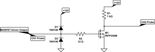
The first waveform is the gate signal and the second one the drain signal with a dummy 1k resistor.

schematic

simulate this circuit – Schematic created using CircuitLab

Thank you,

Riccardo

\$\endgroup\$
21
  • \$\begingroup\$ Please tell us what each trace represents. If (2) should be a square wave maybe you have it set to AC-coupled. 48MHz is an extremely low sample rate for that waveform. A 'real' oscilloscope would sampling at more like 1Gs/s. \$\endgroup\$ Commented Jun 1, 2017 at 16:51
  • 1
    \$\begingroup\$ COuld be anything without a schematic............ \$\endgroup\$
    – Trevor_G
    Commented Jun 1, 2017 at 17:02
  • 1
    \$\begingroup\$ @SpehroPefhany. There is nothing wrong with the sample rate at 48 MHz. If you set the sample rate to Gs/s then with you'd see only a small portion of the waveform! It depends on the length of the capture buffer of course, but most oscilloscopes have quite limited data buffers. \$\endgroup\$ Commented Jun 1, 2017 at 17:07
  • 1
    \$\begingroup\$ You have barely enough input signal to turn on the IRFP250M (VGS(th) is min 2 V), you need to be driving it with more than 4 V peak to ensure it is fully turned on. \$\endgroup\$ Commented Jun 1, 2017 at 17:12
  • 1
    \$\begingroup\$ @TonyM Just measured, 6.47V across those two points. \$\endgroup\$ Commented Jun 1, 2017 at 17:25

1 Answer 1

5
\$\begingroup\$

It looks like you have two (or more) problems. First your output signal appears to be AC coupled so you are not seeing the DC level. But what you would expect in that case would be two spikes, one at each edge of the square wave in opposite directions.

Which brings us to the second problem. You are driving a rather beefy MOSFET with a rather high value pullup resistor at a relatively high frequency. In addition to that your probe with whatever it is connected to is adding even more capacitance. So you see a sharp negative-going spike when the MOSFET turns 'on' but a slow ramp when it turns off.

The capacitance appears still to be quite large compared to the 315pF typical output capacitance of the MOSFET. Check the probe capacitance and use a x10 setting if possible. Also check that the resistor is actually 1K and not 10K (sometimes color codes can be confusing, especially if you mix 4 and 5 band resistors).
\$\endgroup\$
2
  • \$\begingroup\$ Yes, it does seem to be a capacitance issue. \$\endgroup\$ Commented Jun 1, 2017 at 17:49
  • 1
    \$\begingroup\$ Using a ferrite bead on the gate instead of a plain resistor can sometimes help with issues caused by ringing \$\endgroup\$
    – RYS
    Commented Jun 1, 2017 at 18:11

Your Answer

By clicking “Post Your Answer”, you agree to our terms of service and acknowledge you have read our privacy policy.

Not the answer you're looking for? Browse other questions tagged or ask your own question.