0
\$\begingroup\$

I have an MCU application where the MCU switches on/off and monitors the various power supplies of the board (3.3V, 1.8V, 1.0V etc.). When an under- or over-voltage is detected, an alarm to the system should be raised.

Until now the implementation was a bit simplistic: I only took one sample every 5ms and if it was above/below the relevant threshold, for overvoltage/undervoltage respectively, then the alarm was raised.

That led to the problem that on one board, where the dc/dc converter design was not optimal and short over-voltage pulses were present, the alarms were thrown. Such a behavior is of course not desired.

Now I am trying to optimize the c code of the MCU to cope with the problem. I know that ideally this should be solved at its origin (correct the HW design or implement an analog LP filter) but let's assume that this is not possible for the time being.

My first idea was to require more than one consecutive samples to be outside the limits before an alarm is triggered. But somehow I came to this thought: what if I happen to sample exactly when the over-voltage samples occur? I am not sure if they are periodic at all, but it may also be the case. I cannot exclude it. In such a case such an implementation would also fail; it would trigger a false alarm. What do you think? Does this thought make sense at all?

And then my next idea is to implement a digital low pass filter. Probably an IIR recursive filter. But here the questions are even more. Would this really solve my concerns? I mean, if the samples are taken exactly when the periodic pulses come, then the filter solution fails too. Do you have something else to propose? Do you think the digital LP filter is a good idea? If yes, I suppose I should somehow set the 3dB frequency of the filter close to DC. Is that anyhow possible?

\$\endgroup\$
4
  • 2
    \$\begingroup\$ The first thing you need is an exact definition of what an under/overvoltage condition is. Otherwise, the cutomer will always come back saying "that's not what I want". It also sounds that in the problematic board, your monitor did exactly what it should, and that it's the DC/DC converter that should be fixed. \$\endgroup\$
    – jmr
    Commented Jun 7, 2017 at 15:13
  • \$\begingroup\$ The thing is we want to monitor over-voltage conditions in order to protect the expensive ICs of the board (processors, FPGAs etc). In that sense, the short pulses of 5usec that were detected in the problematic boards do not constitute a danger for the ICs. Or at least, we would like to protect against longer pulses. For simplicity let's say we want to protect against DC faults. That is I think our definition. \$\endgroup\$
    – nickagian
    Commented Jun 7, 2017 at 15:21
  • \$\begingroup\$ You should consider FIR over IIR if you end up doing a filter; they are far simpler to implement and unconditionally stable. \$\endgroup\$ Commented Jun 7, 2017 at 15:21
  • \$\begingroup\$ if you sample fast enough then you wont have the aliasing problems you're describing (sampling on periodic pulses).you need to determine the frequency of the overvoltages to determine your sample rate \$\endgroup\$
    – Makoto
    Commented Jun 7, 2017 at 16:28

3 Answers 3

2
\$\begingroup\$

Edit: My original answer did not meet the design goal. This is a different approach.

Count each under and over voltage event. When either count exceeds a threshold of say 3, trigger the alarm.

Reduce the over and under counts each time an in-band reading is taken in order to provide basic digital filtering. Ensure you do not under flow the counters.

\$\endgroup\$
1
  • \$\begingroup\$ Thanks for your answer. You basically describe what my first thought in the second paragraph of your answer. Could you shortly elaborate what you mean by the last paragraph? \$\endgroup\$
    – nickagian
    Commented Jun 8, 2017 at 7:18
2
\$\begingroup\$

The issue with ANY sampling system is it is prone to frequency matching the source signal and if that frequency is undefined you are always in a gamble / probability situation.

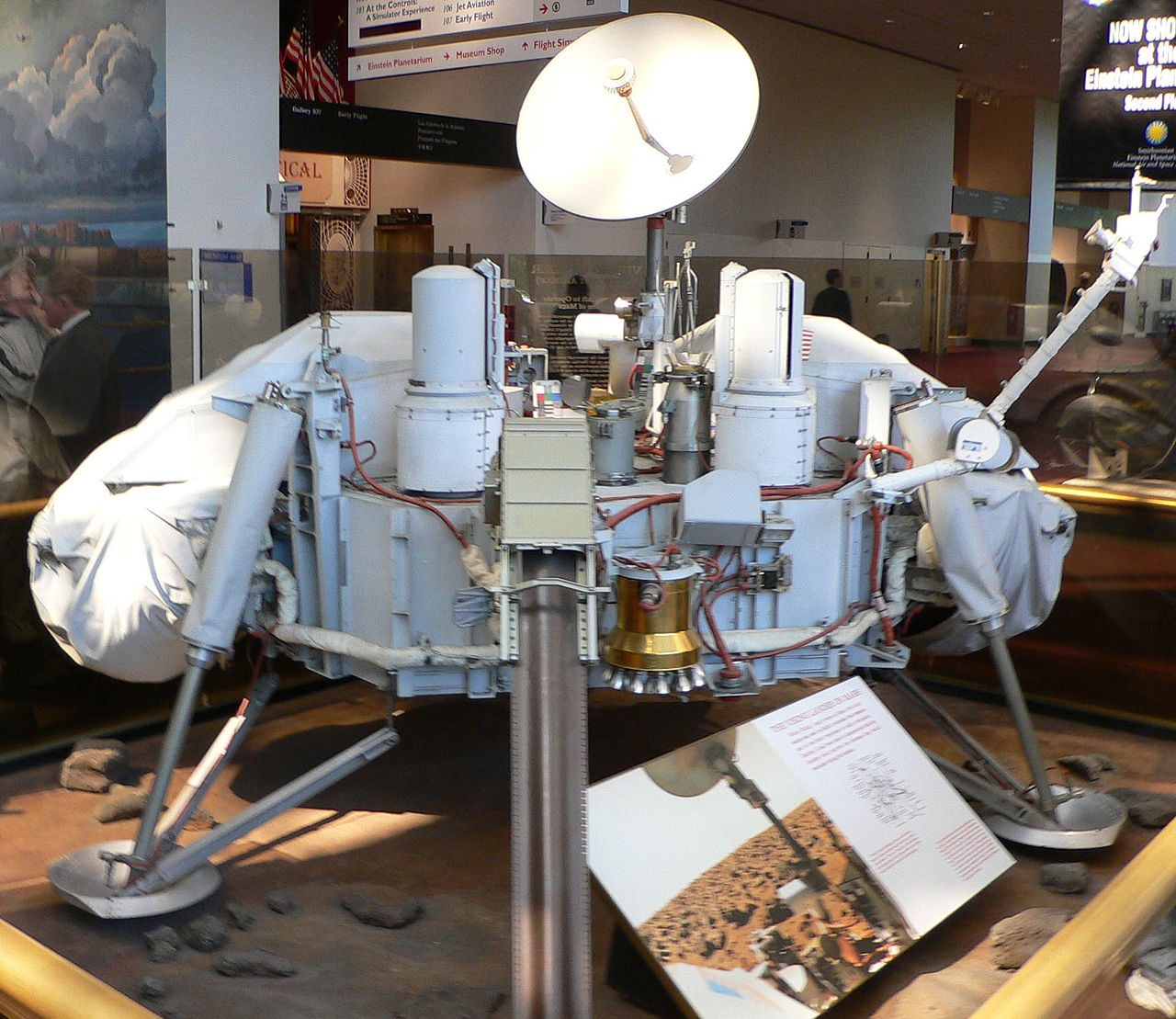
enter image description here

I recall the "Viking" Mars explorer which had a camera which took panoramic pictures by scanning and transmitting vertical lines of image data using a rotating camera head. You can see them as those two vertically slotted pots sticking up in the image above.

It took a wonderful picture for it's time..

enter image description here

Unfortunately, as one of the astronomers on the team pointed out, you could march a brass band past the camera and if the camera took its slices in the gaps in the band, you would never see them.

The same applies to your requirements. You can keep running average values in code, basically creating a low pass filter, and or use an event counter to require multiple out of ranges before reporting, but if things happen to line up with the deviations you will still have the issue.

In addition to those methods I'd suggest, on detection of an errant value, change the sample rate on that particular channel to various time values to try to detect an in-range value. Then when you detect a good value, reset the procedure.

\$\endgroup\$
2
  • \$\begingroup\$ I liked the Viking Mars explorer example! :-) So you do confirm my fear (which of course sounds completely logical) that whatever I do, if the deviations happen to align with my sampling time points, the problem will be there. You suggest using different sampling rates after first detection of an errant value. On what purpose? How will this help? \$\endgroup\$
    – nickagian
    Commented Jun 8, 2017 at 7:24
  • \$\begingroup\$ @nickagian changing the sample rate decreases the probability of harmonic alignment of samples with spikes. The more random the samples the better. \$\endgroup\$
    – Trevor_G
    Commented Jun 8, 2017 at 11:31
2
\$\begingroup\$

As you pointed out, filtering should be done right at the source. Maybe you can place an LC LPF with a cutoff frequency of 10kHz. This should chop off most of the HF content.

But if you have no chance to make a hardware revision then averaging a limited number of consecutive samples will be the simplest solution. About spikes: If you get 10 samples in a short period and 2 or 3 non-consecutive samples show irrelevant values (over- or under-voltage) then just ignore them and average the rest.

\$\endgroup\$
2
  • \$\begingroup\$ Thanks for your answer. So you actually suggest that I should throw away non-consecutive samples that are outside the allowed range. I didn't think of that, sounds a good idea. However, this doesn't help with the situation where consecutive samples do happen to be off-limits. I cannot guarantee that this is a real DC overvoltage or just happened that the spikes are aligned with my sampling points, right? \$\endgroup\$
    – nickagian
    Commented Jun 8, 2017 at 7:30
  • \$\begingroup\$ @nickagian Yes, it's true. But, you can measure the frequency of those spikes by measuring the time difference between them (Note that the spikes show themselves at a rate of DC/DC converter's switching frequency and it can be 50kHz or even 200kHz) so that you can determine optimal sampling rate (at least 2 times that frequency - remember Nyquist). It's unlikely to catch consecutive spikes if you can perform the measurements as fast as this. Anyway, I say again: Put an LC filter instead to get rid of those spikes. \$\endgroup\$ Commented Jun 8, 2017 at 9:09

Your Answer

By clicking “Post Your Answer”, you agree to our terms of service and acknowledge you have read our privacy policy.

Not the answer you're looking for? Browse other questions tagged or ask your own question.