3
\$\begingroup\$

As a heads up, I edited this question to make more sense based on what I have learned. I think this is okay since no one has answered the previous question yet.

So I'm designing a solar system and was looking at the MPPT linked below:

https://www.amazon.com/TRACER-3215RN-Solar-Charge-Controller/dp/B008KWPGAE

I read one of the points of this MPPT was that it uses

  • "4- Stage charge with PWM output."

From that, I know this MPPT uses PWM to adjust the output voltage. I know this is necessary because you need to change your output voltage to fit the rest of your system (as an example system, think of a dc-to-dc step down from 36 input volts to 12 output volts or dc-to-dc step up from 36 input volts to 48 output volts). My concern is this: will this PWM significantly reduce the energy I can get from my solar panels? Let me explain why below:

I'm basically asking if I have PWM technology or a buck-boost converter that deems I need a duty cycle of 0.4 to reach the voltage I want (this means the switch is open on the buck-boost converter or PWM circuit 60% of the time), does that mean I don't generate power with my solar panels 60% of the time? For example, think of a natural gas generator that runs 8 hours a day but you only have a load plugged into it for 40% of those eight hours. That's a lot of natural gas wasted. Similarly, I'd lose 60% of my insolation on my solar panels, right? Since they only actually generate power 40% of the time since the switch is open the other 60% of the time on my PWM circuit or buck-boost converter.

\$\endgroup\$
14
  • 2
    \$\begingroup\$ No, MPPT is not PWM at all. But I will leave it to others to explain why. Suffice it to say that with MPPT you can feed it much higher voltages (like all your panels in series) and it will convert that excess voltage into current for your batteries. \$\endgroup\$
    – SDsolar
    Commented Jun 11, 2017 at 0:32
  • \$\begingroup\$ But it has to step up or down the voltage somehow to integrate with the rest of my circuit, right? Like the one I linked says specifically that it uses PWM for the output. I know MPPT differs from PWM for the input since MPPT can determine the maximum power point for a solar panel, but PWM is still needed for the output voltage, correct? \$\endgroup\$
    – MechE
    Commented Jun 11, 2017 at 0:36
  • \$\begingroup\$ You know, since this question has gone way off the original question. I think I am just going to make a new question for clarity. It makes no sense to ask about the difference between buck-boost converters and PWM and then ask about something different in a spin off. \$\endgroup\$
    – MechE
    Commented Jun 11, 2017 at 1:27
  • 3
    \$\begingroup\$ It's entirely possible that an MPPT controller also uses PWM. The distinction is to say that PWM (to limit voltage) is the only thing it does. Whereas MPPT is doing a lot more complicated stuff: scanning/hunting V or I dynamically to maximize watts. Having done so, it must now buck down to correct battery voltage. \$\endgroup\$ Commented Jun 11, 2017 at 1:29
  • 1
    \$\begingroup\$ You are mixing independent terms that are used together BUT are different things: PWM = = off/on switching. || Buck converter = energy gearbox that takes eg high V low I and converts to lower V higher I with SOME losses. || A good buck converter gives >= 90% efficiency. Power losses drop in approx proportion to load drawn (not quite but close enough). || MPPT is a system which uses eg PWM switched eg buck converter and adjusts PWM ratio to optimise energy transfer efficincy. || SO MPPT optimises energy transfer efficency for a give insolation (solar input) level and a given load. \$\endgroup\$
    – Russell McMahon
    Commented Jun 11, 2017 at 8:01

3 Answers 3

5
\$\begingroup\$

if I have PWM technology or a buck-boost converter that deems I need a duty cycle of 0.4 to reach the voltage I want... does that mean I don't generate power with my solar panels 60% of the time?

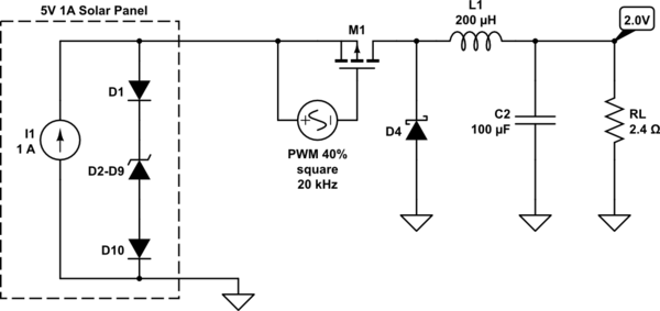
Not if the converter is properly designed. You are probably thinking of a buck circuit that looks like this:-

schematic

simulate this circuit – Schematic created using CircuitLab

If it was this crude then you would be correct to assert that the solar energy would not be fully utilized, because current would only be drawn from the panel during the 40% PWM on-time.

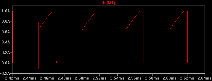
I simulated this circuit in LTspice and graphed the current through M1 (which is essentially the same as the solar panel's output current):-

enter image description here

When the FET is turned on it draws up to 1A from the panel, but when off it draws nothing! 60% of the time the panel absorbs the solar current internally, wasting it. As a result the power output is only 1.7W, nowhere near the expected 5W.

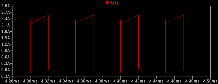
But there is something missing from this circuit that all properly designed converters have - a reservoir capacitor across the input. After adding a 220uF capacitor across the panel, and lowering RL to 0.85Ω to maintain 2.0V output, the current through M1 looked like this:-

enter image description here

The reservoir capacitor eliminates the 1A current limit, so the converter is now able to draw up to 2.6A (1A from the panel plus 1.6A from the capacitor) producing 4.8W at the output - 96% of the panel's capacity. During the 60% PWM off-time the solar panel recharges the reservoir capacitor at 1A, so it is always working at full capacity.

\$\endgroup\$
5
  • \$\begingroup\$ PWM is constantly adjusting the duty cycle. It definitely isn't fixed. \$\endgroup\$
    – SDsolar
    Commented Jun 11, 2017 at 22:34
  • \$\begingroup\$ 40% PWM was specified in the question. 5V * 40% = 2V. I manually adjusted the load to meet those conditions at maximum panel output power (5V * 1A) because that is the scenario being considered. Of course an MPPT controller will automatically vary the PWM to suit changing conditions. \$\endgroup\$ Commented Jun 11, 2017 at 23:57
  • \$\begingroup\$ Ah. I didn't catch that in the question. Point of order: MPPT controllers may be switching but they are definitely not like PWM which directly switches between the battery and the panels. They are more like the power supply in your computer. 40% PWM is completely arbitrary. But I get your point. \$\endgroup\$
    – SDsolar
    Commented Jun 12, 2017 at 0:31
  • \$\begingroup\$ I do a fairly decent job of describing it in my first blog post. You might enjoy this: en.wikipedia.org/wiki/… \$\endgroup\$
    – SDsolar
    Commented Jun 12, 2017 at 0:37
  • \$\begingroup\$ This is exactly what I was asking. Good to know that the devices are smart enough not to waste energy generation time. Of course the other answers are helpful as well, but this one was the most clear for me. \$\endgroup\$
    – MechE
    Commented Jun 12, 2017 at 0:37
2
\$\begingroup\$

Updated

4- Stage charge with PWM output; only deals with the needs for different battery chemistry. Like ESR Voc test, CC low charge at high ESR, high CC when ESR drops, then CV then Shutdown then Ich drops below 10%.

That has nothing to do with MPT conversion but is essential to be integrated with MPT conversion for LiPo or Sealed Lead acid or whatever.

Next what does MPT really mean? When does Maximum Power Transfer occur? Answer: conjugate matched impedance Z (f).


You have Voc and Isc coming from the PV in two distinct impedances, "open circuit and short circuit" . How do you achieve maximum power transfer? ( Moritz von Jacobi published the maximum power (transfer) theorem around 1840; it is also referred to as "Jacobi's law".)

The theorem results in maximum power transfer, and not maximum efficiency. For a voltage converter, you want maximum efficiency but for a power converter like a PV you want maximum power transfer to capture all the power that is available.

This is done by conjugate impedance matching a switched inductor using primary PWM to store energy from a PV current source with a capacitor load on input such that the average impedance of the switched inductor over one cycle is EQUAL R (but opposite reactance, X(f)) at some frequency , f. Then can expect Jacobi's Law to work.

However for voltage regulation and high efficiency, in voltage step down or up converters you want any load to have minimal effect on the regulated voltage. Therefore the voltage ratio , n leads to an impedance ratio n^2 and using simple math of an impedance divider tells you the source must be mcch lower impedance than the load. i.e. Vdrop=Rs/(Rs+Rload)Vs so a 1% Vdrop variation with load implies the source Z must be 1% of the load Z(referred to the source) using n^2 from voltage ratio. Go read

Using a simple switched voltage converted from 24 or 36 to 12V assumes a low impedance source to have high efficiency. THis does NOT work from a Current Source.(PV)

Solar Panels can be modeled as sun controlled current sources (high impedance) with a zener voltage limit (Voc) when open circuit.

When loaded at MPT the PV voltage drops only about 15to25% for optimum VI. Reducing by 50 to 75%voltage reduces the power out = VI

You can convert the Norton equivalent circuit to a Thevenin with some load testing and actually limit the current load if the input power gets reduced using a few transistors and zener with an optical PD to regulate the current limit.

But most people buy an MPPT convertor to do this. Some hunt for max power by sensing current and voltage in and out, others use an algorithm based on pulsed no load Voc and other methods are documented in this forum.

Whereas a SMPS voltage converter assumes the source is a low impedance voltage source to achieve maximum efficiency. The input current to a SMPS depends on the demand charge for the battery charger.. SO there must be two separate conversions. One for effectively matched impedance to the PV that limits current out with solar input. One for voltage regulation and output current to the battery according to State of Charge and current limits imposed. e.g. CC till Vbat rises to Vx then CV according to other chemistry requirements.

So an ideal PV converter needs 2 stages of regulation to utilize the maximum power transfer theorem because the PV is not a voltage source.

It is possible to combine these two regulators into 1 by using one or more Photo Diodes (PD) for redundant feedback.

BTW other newable power sources also have this characteristic where the impedances must be matched at maximum power transfer. Wind, water , nuclear (?) THis means the demand load never exceeds the supply power at some incremental V/I impedance. For example excess load would act as a brake to window power turbine and thus reduce the available wind energy and optimum RPM at max Hp.

\$\endgroup\$
18
  • \$\begingroup\$ But does using PWM make you lose some energy generation potential? I feel like you explained how MPPT works, which is cool, but I'm more asking this: If I use a buck-boost converter or PWM to reduce or increase my input voltage to a desired output, I am using a switch with a duty cycle, right? When that switch is in the open position, no energy can be generated by the PV panels, right? So if I had a duty cycle of 0.4, 60% of the time I'm not generating energy, right? \$\endgroup\$
    – MechE
    Commented Jun 11, 2017 at 2:28
  • \$\begingroup\$ @MechE. In practice there would there would be a large capacitor at the input that would be storing the energy during that time to make it available during the ON part of the cycle. \$\endgroup\$ Commented Jun 11, 2017 at 2:47
  • \$\begingroup\$ @Kevin White So I'm not losing energy generation time is what you're telling me? Seems kind of hard to believe that a capacitor could store 60% of the solar panel's energy generation (assuming a duty cycle of 0.4). I mean, what about for like a buck converter where you have to step down the voltage? Edit: Oh wait...maybe that would work. But doesn't a capacitor give you a really high voltage? Seems like that wouldn't work for a buck converter. \$\endgroup\$
    – MechE
    Commented Jun 11, 2017 at 2:51
  • \$\begingroup\$ @Tony - A PV cell is better modeled as a light controlled current source in parallel with a diode rather than a zener. It should have a logarithmic current/voltage response. \$\endgroup\$ Commented Jun 11, 2017 at 2:51
  • 1
    \$\begingroup\$ @MechE - why not? It just means that the capacitor value needs to be defined to meet the required ripple voltage requirement at the input. The capacitor only has to store the energy until the next PWM cycle. \$\endgroup\$ Commented Jun 11, 2017 at 2:53
0
\$\begingroup\$

The short answer is no.

PWM controllers are just fast switches.

When the conditions are such that the power is in excess of what can be used, the switch opens up. It does it in pulses as it attempts to regulate the voltage. Hence the name pulse-width modulation. It is never fully off - just the duty cycle changes to adjust. So yes, power is not used but it is power that couldn't have been used. Like when the battery is full and there is no other load, like an inverter..

But when the battery is not full, or you are pulling other loads from it, the pulse-width gets to be nearly at a 100% duty cycle - meaning that all the energy the panels can produce is transferred.

PWM pulse-widths are continually changing depending on the load and type of battery. You don't want sealed lead-acid batteries bursting, nor do you want open flooded batteries boiling dry. So it quenches the power to keep things regulated. In the end you get all the power you can be used but any reduction is not due to inefficiency. It is under program control.

Wikipedia definition of PWM with diagrams

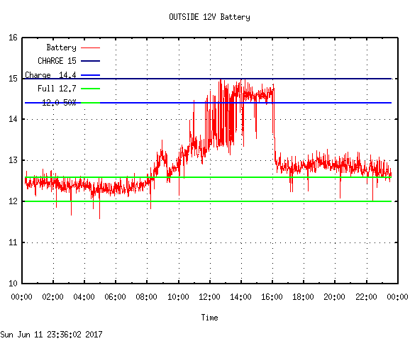
Here is today's plot of my secondary PWM charger with a 50 Watt panel on a 12 Volt marine battery - it powers the motors which aim my soar panel pairs. (The downward spikes are when the motors (3 of them) activate to reposition the panel pairs)

You can really see how the pulses work, on a cloudy day :
enter image description here

This is very bad for my ham radios. It generates a lot of radio noise.


The PWM charge controller is just one piece in the overall system. Every single device or connection in the system is going to lose some power.


My MPPT charge controller is about 90% efficient. My oversize inverter is about 92% efficient. If you plug in anything with a power converter in it (like a laptop charger), then you lose another 10% or so.


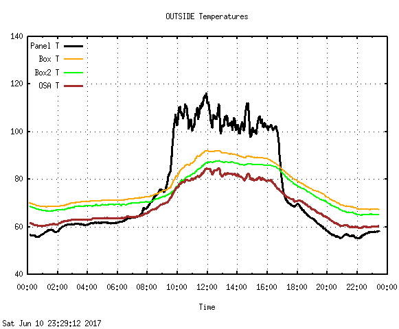
The BIG ONE is that solar panels are tested at 68 degrees. But mine get up to about 120 while operating here in the desert so there goes another 20-25%. Doesn't matter what kind of controller you use. That's just physics. Batteries get more efficient as they get warmer, but solar panels get less efficient as they get hot.

Check out the kind of temperatures I have to deal with:enter image description here

Using higher voltages is why the MPPT controller is a much better choice than a PWM controller for any non-trivial system. Cable is expensive. Just like the power company - their long-haul lines can be up in the 100KV range, and they still use wires that are about 3 inches thick. That is many dollars per foot.

With PWM you do not have the option of running such high voltages. Your input voltage can't be very much higher than the highest charging voltage or the controller will dissipate the difference as heat. (There are losses in everything, remember - thermodynamics - even the transistors that do the switching) Hence the cooling fins on them. My original 12V system took a lot more amps because the volts were so low.

$$ P = V \times A $$

So now with the MPPT Tracer Commander I run 120V at just a few amps, running through 8 Gauge cables.

The size of the cables is determined by the square of the amps. So if you cut the voltage in half you need to double the amps and have have 4x less resistance in the cable to run the amps you need to get the same amount of power transfer.

Cable is sized by using this rule:

$$ P = A^2 \times R $$

If you want the same power at one third the voltage then you need 9 times less resistance because of all the extra Amps required to carry the same amount of power. That translates to needing much thicker cables for low-voltage systems.


That's what killed off the Edison power stations when Tesla came along with AC that could be stepped up in voltage. Edison had to deliver it at the voltage at which it was being used. He had to have power stations every few miles because of resistance losses in his DC cables. We all know the rest of that story.


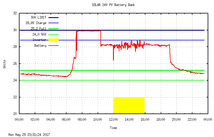
I have 6 panels wired in series, (that's up to 120 volts), so the MPPT Tracer controller converts that to the optimum voltage for my 24V 500Ah battery bank (Near 30V for Boost phase, less for Float phase) plus all the gadgets I run both from the inverter and straight from DC.

Wikipedia Definition of Maximum Power Point Tracking

Here is a plot showing the action of the Renogy Tracer Commander MPPT controller. Not at all the same as the PWM unit. This one is running 6 100W panels in series (up to 20 volts each for a total of 120VDC) into 4x 122 Ah deep-cycle Marine batteries wired in series/parallel (24 V bank) and the yellow section shows when the inverter is on, running all the lights and computers. Again, this was a cloudy day but look at how the MPPT controller maintains the voltages because it has so much to work with:
enter image description here


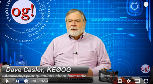
If you want to learn about how the various kinds of controllers work, please allow me to recommend that you watch this video:

** -----> https://youtu.be/g-hqt6pvGxo <-----**
enter image description here

In it, KE0OG, the Original Genius, explains it all for you.

One thing he stresses does not affect me - the partial shadowing. It used to be true that just a tiny shadow on the corner of a panel could cause them to entirely quit working. But my panels have bypass diodes at each cell so the power just goes around the shadowed cells.

Also, I use flooded lead-acid deep cycle Marine batteries. Yes, I have to check them periodically, but the MPPT charger keeps the voltage under control so they do not boil the water away. The fastest way to kill a battery of this type is to let it expose any of the plates to the air. I keep them in Marine battery boxes so there is no acid gasses inside the home.

Since mine follow the sun I can fit 6 panels in the space I have available and get enough power for 24 hour operation.

Towards the end there is a cameo of my system shown. He thinks I have gone a bit overboard. My panels swivel to follow the sun, for instance. If they didn't, I would need twice as many to get the same total power in a day.


Think of it like this: You have a spigot for water outside your house (or in your kitchen). Even when it is shut off there is pressure - that is volts. Then when you hook up a hose to run a sprinkler and turn on the spigot you have water flowing - that is amps. And if you are using it to fill a bucket then that is Watts. The amount the bucket gets full per hour is Watt-hours. In a day, you want as many Watt-hours as you can get. The batteries are the bucket. But it also has a spigot that runs my gadgets.

The trick is to keep the bucket full enough that you have water all night when the sun isn't shining. In my case, I have automatic lights for the kitchen and bathroom, etc., that turn on when someone is there, so I am using the sun's power at night because I stored it up during the day.


This video explains the fundamentals and decisions to make in building out a solar power plant. Choice of a charge controller is front and center in the explanation.

In the end you will see why the Tracer is worth the cost.

Have fun!

https://www.google.com/search?q=david+casler+solar+power+for+a+ham+station.

\$\endgroup\$
4
  • 1
    \$\begingroup\$ PWM comment is not really correct. I imagine you know and understand the following, but your answer needs to be altered to clarify thiese points: As devices sold as "PWM controllers" may have no conversion functionality and may just be on/off switches, they may reduce energy compared to what the panel could optimally deliver. If eg a PV panel delivers 18V at 10A and is connected to a 12V battery it can deliver 10A max. If you add a buck converter with MPPT control at say 90% efficiency you can get 10 x 18/12 x 90% = 13.5A at 12V.... \$\endgroup\$
    – Russell McMahon
    Commented Jun 11, 2017 at 8:07
  • 1
    \$\begingroup\$ SO a PWm modulated buck converter with MPPT control optimises energy transfer. Whereas a PWM on/off switch reduces available panel energy. \$\endgroup\$
    – Russell McMahon
    Commented Jun 11, 2017 at 8:07
  • 1
    \$\begingroup\$ My system would be more complicated than just a battery. I want to use all the energy my solar panels can generate all the time either burned through a load or, for the sake of my question, an infinitely large battery. My concern was that some batteries need 12/24/48V dc to charge. PWM has a duty cycle e.g. 0.4. I did not want to lose energy generation time on my solar panels by having the switch open 60% of the time to reduce the voltage to the desired level for my system. \$\endgroup\$
    – MechE
    Commented Jun 11, 2017 at 18:22
  • \$\begingroup\$ "The amount the bucket gets full per hour is Watt-hours." -no, that is not an accurate analogy. \$\endgroup\$ Commented Feb 13, 2018 at 22:28

Your Answer

By clicking “Post Your Answer”, you agree to our terms of service and acknowledge you have read our privacy policy.

Not the answer you're looking for? Browse other questions tagged or ask your own question.