4
\$\begingroup\$

When the resistance of a MOSFET at a certain gate voltage and current is needed, the correct value is ordinarily obtained by reading the datasheet for specified values.

Since a MOSFET is supposed to act as a resistive component, how good would results of measuring the resistance between drain and source be? I know that the current affects the resistance, but I plan to run the MOSFET at low enough current so that the effect shouldn't be too important.

\$\endgroup\$

3 Answers 3

4
\$\begingroup\$

You can measure Rdson under the conditions that you specify, BUT your measurement conditions will be so different from what you would normally experience that you will need to be very careful to ensure that it tells you what you want to know.
Most meters use a 9V battery (6V-9V) but some use 2 x AA = 2 to 3V and some use 1 x AA (rare).
Meter current may be 1 mA or some other current. The lower the test current the less the test will be like most real world conditions. If your Itest is 1 mA and Icircuit is going to be 10 mA then results may be quite different.
Ambient temperature will affect results.

You may have a good reason for doing this rather than by using the data sheet but it is not at all apparent what useful purpose would be served. You will get a one off result in a very special and uncertain circumstance that may be quite different than what you will get under similar circumstances subsequently.

MOSFET Rdson is dependent on Vgs. For Vgs more than a few gnat's whiskers above Vth - the gate threshold voltage , Rdson will be about as low as you can get for that device. But if meter current is say 1 mA and you increases Ids to say 10 mA you may* find that Rdson increases very substantially.

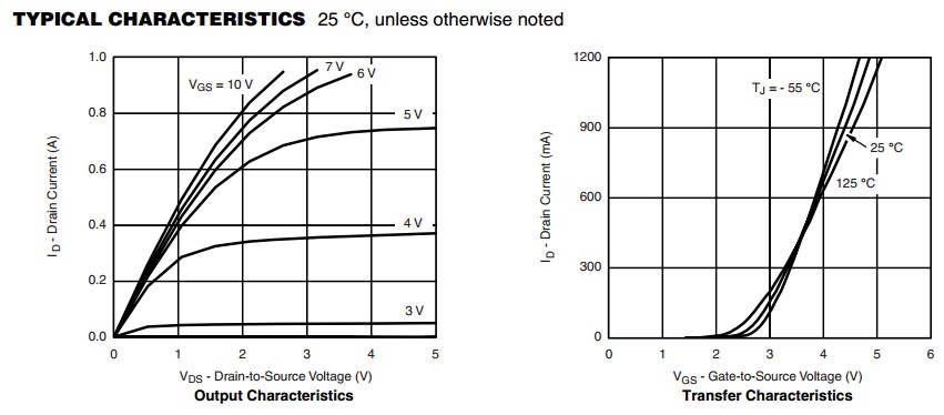
Below are Ids versus Vgs curves for a 2N7002. It can be seen in the left hand graph that for Vgs = 10V the Rdson is about R=V/I = 0.85V/0.4A say ~= 2.1 Ohms. For high values of current curves for lower Vgs curve off to the right - ie Rdson increases markedly above a certain Ids in each case. BUT for a low enough Ids the curves all tend to asymptote to the same as the Vgs=10V line. It may not appear that the Vgs=3V lines does this but that is mostly due to the scale of the graph axis. The right hand curves show the relatively linear behaviour of Rdson with Vgs at a fixed temperature down to Vgs ~= 3V at 25 degrees Celsius.

enter image description here

An alternative to relying on relatively undesigned meter based voltages and currents is to place a resistor Rd in series with the drain and apply Vgs as desired then measure Vds and (Vsupply-Vds) = Vresistor.
Then Ids = Vresistor/ Rd.
Vds = measured. Vgs = as set by you. Then Rdson = Vds / Ids.

A technically superior alternative is to set up a variable power supply to current limit at design current - say Ids = 10 mA, and apply Vgs as desired.
Measure Vds and all done.
Rdson = Vds / Ids

If you do use the meter method then adding a series resistor Rd will allow you to both measure meter current and to check the result as above.
You'd need a separate voltmeter.

\$\endgroup\$
3
\$\begingroup\$

Yes, you can measure Rds_on of a MOSFET using an ohmmeter (probably you will need a miliohmmeter), but just remember (as you say) that that is the measure of Rds_on at the specific Vds that your ohmmeter is causing to appear there (and also, of course, at the Vgs you are applying). Rds_on is a nonlinear resistance.

Since the current injected by the ohmmeter depends on the scale selected, and Vds depends on that current, the nonlinearity of Rds_on will make you see slightly different readings at different scales. If you want to compare several MOSFETs, just use the same resistance scale. If you want to know at which Vds an Rds_on reading has been taken, just measure it with another tester, configured as a voltmeter.

\$\endgroup\$
2
\$\begingroup\$

You can do this, but it will only be valid at the operating point produced by your multimeter.

The multimeter will apply a small, regulated voltage to the circuit through a resistance which varies in value depending on the scale in use. The voltage across this resistor is measured with an ADC and the resistance of the attached resistor can be computed from this reading. For my Fluke meter, the resistance mode has the following characteristics:

Fluke 289, see p. 77

which shows that the MOSFET will see a \$V_{DS}\$ of less than 550 mV (how much less depends on the result) and a current of less than 1 mA (again, how much less depends on the result). If you have a second meter, you can use it to measure the voltage and current being applied. If these values are the same as your target application, it will work. They're likely not.

In the cutoff region, where \$V_{GS} < V_{th}\$, the resistance is very high and more closely related to \$V_{GS}\$ and \$V_{th}\$ than \$V_{DS}\$. Your multimeter will not produce a good reading in this region simply because the answer is probably greater than the maximum resistance that your meter can display.

In the saturation region, where \$V_{GS} > V_{th} \$ and \$V_{DS} > ( V_{GS} – V_{th} ) \$, the current is the approximately the same regardless of the applied voltage. Again, the multimeter won't do a very good job in this state for two reasons: First, it's nonlinear, and second, it's very low but requires a high \$V_{DS}\$. Unless you're using cheap or old MOSFETs and an overzealous multimeter, you won't get accurate results here.

However, in the triode or linear region, where \$V_{GS} > V_{th} \$ and \$V_{DS} < ( V_{GS} – V_{th} )\$, the MOSFET will behave mostly like a resistor and have a resistance in the range which your meter can measure. I say mostly because it gradually transitions into the saturation region; as \$V_{DS}\$ approaches \$ V_{GS} – V_{th} \$ it becomes more and more nonlinear. You should get good results here, but you won't know without testing with another multimeter whether you're in this region. At that point, you may as well set up a curve tracer if you've got an old HP4151B or something similar in the lab. If not, a crude, manual curve tracer can be constructed from a function generator that sweeps through a voltage range, a sense resistor, and an oscilloscope which monitors the current through the sense resistor on one channel and the output voltage on another.

In conclusion, the multimeter is only useful in the triode region and even then it's better to use a curve tracer.

\$\endgroup\$

Your Answer

By clicking “Post Your Answer”, you agree to our terms of service and acknowledge you have read our privacy policy.

Not the answer you're looking for? Browse other questions tagged or ask your own question.