0
\$\begingroup\$

I have a question regarding using an n-channel mosfet in the high side with a charge pump bootstrap.

Lets assume the following:

  • Vgs max is 15v
  • Vgs(th) is 2v (logic level)
  • voltage pressent at source pin is 10v
  • charge pump is charged to 20 volts
  • all grounds are common

Now, the voltage at the gate must be higher than the source to turn on. Since the source pin is at 10v, the gate must be at least 2 volts (Vgs(th)) higher. So you have to apply at least 12 volt to the gate, so that the fet can turn on. Now if i apply the output of my charge pump to the gate with the help of a transistor ( and here is the real question ) what voltage does the gate of the fet see ?

Is it 20 volts ? Bad because Vgs max is 15v. Or does it see 10 volts ? (20v pump - 10v source = 10v gate ?)

And if it sees only 10v, why or how ? I ask why, because i dont understand why its 10v even though im applying 20v.

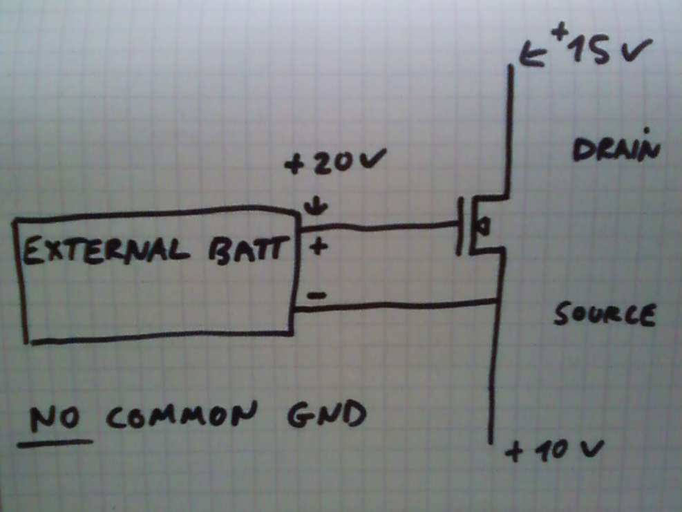
Second question: Would it be still 10v at the gate if i use an external 20v battery with no common ground. + of the battery to the gate and - to the source ( which is at 10 volts )

Thanks

Edit: Added schematics for this example.

enter image description here

Edit2: Added second schematics for my second question. (ofc there isnt a common gnd, but just saying) Edit3:( Only the +15 volts gnd is the same gnd as the 10 volts battery )

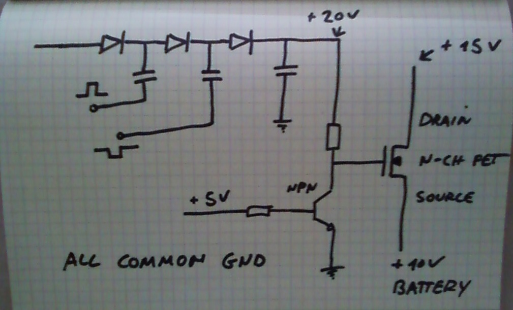
enter image description here

\$\endgroup\$
2
  • \$\begingroup\$ Schematic please. \$\endgroup\$
    – winny
    Commented Jun 25, 2017 at 10:45
  • \$\begingroup\$ There isnt realy something i want to build, i just asked because i dont understand the voltages present on different points. But i drew one, i upload it in a second. \$\endgroup\$
    – stackonaut
    Commented Jun 25, 2017 at 11:12

2 Answers 2

1
\$\begingroup\$

Is it 20 volts ? Bad because Vgs max is 15v. Or does it see 10 volts ? (20v pump - 10v source = 10v gate ?)

And if it sees only 10v, why or how ? I ask why, because i dont understand why its 10v even though im applying 20v.

The gate will be at 20 volts and the source will initially be at 10 volts. That's a gate source voltage of 10 volts and within spec. Voltages are always relative.

Second question: Would it be still 10v at the gate if i use an external 20v battery with no common ground. + of the battery to the gate and - to the source ( which is at 10 volts )

If you apply a 20 volt battery between gate and source then you have a problem irrespective of what other circuitry is raising the source to whatever potential.

\$\endgroup\$
4
  • \$\begingroup\$ But if voltages are relative, why does it not work with the battery. Isnt the gate still 10v higher relative to the source ( which is 10v in my example ) ? \$\endgroup\$
    – stackonaut
    Commented Jun 25, 2017 at 10:41
  • \$\begingroup\$ If the source is at ten volts with respect to ground, the gate has to be at thirty volts because the battery sets the gate voltage twenty volts higher than the source \$\endgroup\$
    – Andy aka
    Commented Jun 25, 2017 at 11:39
  • \$\begingroup\$ Im confused tbh. I found this video and hes doing "exactly" what i try to understand. Why does it work what he is doing with the external battery, but mine does not as you say ? youtu.be/ZZDdlAgZfvI?t=3m22s And even then...i still dont get why with the charge pump (see first picture) the gate is 10v above source, but with the external battery that has the same voltage as the charge pump its not. \$\endgroup\$
    – stackonaut
    Commented Jun 25, 2017 at 12:14
  • \$\begingroup\$ I'm not watching a video sorry. What I'm saying is really quite sinmple - the battery defines the voltage between gate and source if it connects directly to gate and source. \$\endgroup\$
    – Andy aka
    Commented Jun 25, 2017 at 12:29
0
\$\begingroup\$

\$ V_{GSth}\$ is irrelevant, you want to look at the datasheet specification for \$ V_{GS}\$ which gives you the \$ R_{DSon}\$ you want. A logic level FET will have its \$ R_{DSon}\$ specified for \$ V_{GS} = 5V\$.

So you can replace all the instances of "at least 2 volts" in your text with "At least 5V". Unless you use a 1.8V specified FET, in which case it will turn on with 2V. A 5V FET won't turn on. \$ V_{GSth}\$ is the voltage when current starts to flow, ie a few µA. You can't switch a load with that.

Now, the bootstrap driver. If you look at a datasheet for a half-bridge driver such as this one you'll notice that the bootstrap cap negative pin is on the MOSFET source. So the bootstrapped supply is referenced to the MOSFET source, which avoids any \$ V_{GS} \$ overvoltage issues.

So, you do something similar.

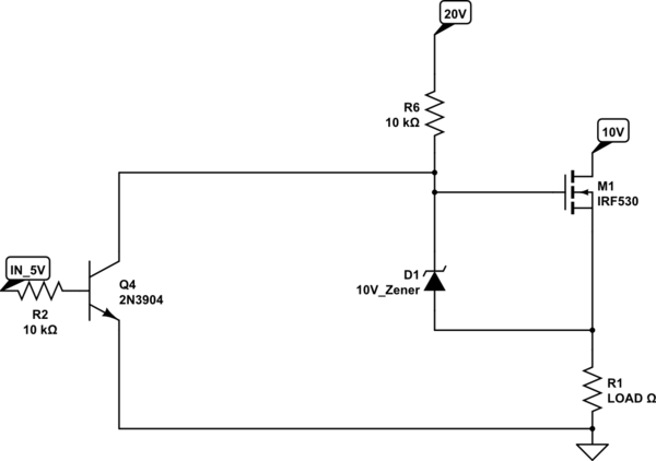
If a higher supply is available (you mention 20V) then you could do something like that:

schematic

simulate this circuit – Schematic created using CircuitLab

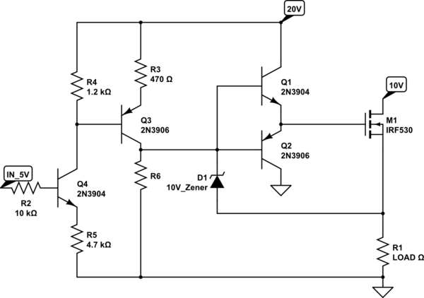
However, turning on the FET will be very slow due to the 10k pullup. I presume you used a NMOS for speed (else you'd have used a much simpler PMOS), so then you'd need a more complicated driver:

schematic

simulate this circuit

...and this circuit is completely useless, since... if you want speed, it means you're doing PWM, and in this case using a dedicated driver like the ADP3120 (or equivalent) I linked above would be both easier and cheaper. Granted, ADP3120 can't stay ON continuously since the bootstrap cap needs recharging, but you can limit your PWM to 99.9% so it's not a problem.

\$\endgroup\$
1
  • \$\begingroup\$ Sometimes 95% is the maximum... Depends. \$\endgroup\$
    – user76844
    Commented Jun 25, 2017 at 10:00

Your Answer

By clicking “Post Your Answer”, you agree to our terms of service and acknowledge you have read our privacy policy.

Not the answer you're looking for? Browse other questions tagged or ask your own question.