4
\$\begingroup\$

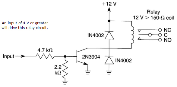
I found this circuit for a relay driver. It is similar to others I have seen, though it appears to have two extra parts that others do not have.

I mostly understand how it works, but I would like to understand it thoroughly, so I have some questions in my attempt to analyze it. This is not homework for a class. Rather, I am attempting to educate myself. My questions come after studying tutorials online, but I still have questions.

enter image description here

  1. I usually see an input-base resistor around 4K7. I think it determines the current flowing from base to emitter when an input is applied. I think it needs to be high enough for the transistor to saturate, and no more than the maximum CMOS load, which I think is 20mA.

I want to understand why the resistor is 4K7. My analysis: The Vbe(sat) for the 2N3904 is about 0.7v. If the input voltage is 12v, the load on the input voltage is (12 - 0.7) / 4700, or about 2.3mA, ok for CMOS. I have a 12v relay that has a DC coil resistance measuring 392R, so at (12 - 0.7)v, that means about 29mA to actuate it (too much for a CMOS load without a driver). The 2N3904 has a beta / hFE of 300 (max), so the minimum Ib I need for saturation is 29mA / 300, or 96uA, though it should be higher to be reliable. I think the input base resistor could be as high as (12 - 0.7)v / 150uA, or about 75K, but a lower value would be more reliable for a wider range of loads.

With the 4K7 resistor, 2.3mA is the load at 12v input, so a load of (300 * 2.3mA) or 67mA is possible. The 2N3904 can dissipate 200mADC, but for a load that high, the 4K7 resistor would be more like 1K5.

Is my analysis correct?

  1. This circuit adds a 2K2 resistor from base to emitter (ground), something I do not usually see in other circuits. I think this may change the bias voltage for the transistor, but I don't know why you would do that here. What is the purpose of this resistor, i.e. what problem does it solve?

  2. For relay control, I always see a "flywheel diode" across the relay, with anode at transistor collector and cathode at Vcc, as shown in this diagram. I understand that the inductive effect of the relay coil causes a backward voltage spike to occur as the magnetic field collapses, and the diode protects the transistor from too large a reverse spike.

I think if I connect a diode across a power supply with anode at Vcc and no current limiting resistor, it will burn out. The backward spike would seem to do the same. Can you explain why it does not? Is it because the spike is too brief to burn out the diode?

  1. Most circuits have only the one diode across the relay, but some also have one from the emitter to the collector. This circuit has one (it is not certain that it is actually connected to the collector, as there is no junction dot in the diagram there). I have a feeling there is another spike, perhaps on power on, but I don't know why that would happen, and I would like to understand. What problem does this second diode solve?

  2. I have a new oscilloscope, but I don't know how to apply it to this circuit. In particular, if there is a transient across the relay when it turns off, do I simply connect the scope across the relay to see it? If the answer to #4 is "another spike," where do I connect the scope to see it, across C and E? Do I have to remove the second diode to see it?

  3. Do you think that this is a suitable circuit using best practices? If not, please critique.

\$\endgroup\$
4
  • \$\begingroup\$ A lot to read. But one thing stood right out to me: "ok for CMOS". The BJT is not CMOS. Just a note. \$\endgroup\$
    – jonk
    Commented Jun 25, 2017 at 16:34
  • \$\begingroup\$ youtube.com/watch?v=c6I7Ycbv8B8 ("#183: Why diodes are used around relay coils: Back to Basics on flyback or snubber diodes") is a video where W2AEW shows exactly what you want to see. \$\endgroup\$ Commented Jun 25, 2017 at 18:15
  • \$\begingroup\$ that youtube video is very helpful. I suspect I will be watching many of his other videos. Thanks. \$\endgroup\$
    – Mark Colan
    Commented Jun 25, 2017 at 22:21
  • \$\begingroup\$ Related to 4: as per "Practical Electronics for Inventors" by Scherz page 413 there seems to be a negative spike + oscillations on the collector in the brief period when the transistor is switched on (due to coil imperfections: inductance, capacitance and resistance). The second diode seems to make sure it doesn't go out of hand. \$\endgroup\$
    – akhmed
    Commented May 14, 2018 at 22:41

3 Answers 3

2
\$\begingroup\$

Answering your questions in order-

  1. If you look at beta(min) it is specified with a rather large Vce. Usually we want to ensure saturation in the transistor. In the case of 12V we might be able to live with a 1V drop across the transistor but it will compromise the relay life a bit and is not good practice. See the diagrams in this [datasheet].

enter image description here

The Vce(sat) is guaranteed at a forced beta of 10. In other words, you give the base 10mA to get the collector to switch 100mA. 20 is probably safe here, so let's use that. With a 4V input, the 4.7K will pass (4V - 0.7V)/4.7K = 0.7mA. The 2.2K resistor eats almost half that, leaving 380uA for the base. Using the 20:1 ratio, the collector can switch 7.6mA, which isn't much of a relay coil.

  1. The 2.2K resistor prevents AC picked up by the input lead (or DC leakage) from turning the transistor on partially if the lead is open circuit. It also could prevent damage to the transistor from applied negative voltage. The transistor is guaranteed to withstand Veb of 5V maximum, so you could apply more than -15.6V without violating that limit.

  2. The 'spike' does not exceed the relay coil operating current (it starts there and tails off) and it is brief (milliseconds). It does not stress the diode much at all.

  3. At the risk of sounding snarky, I don't see any problem it solves other than an excess of diodes in the storeroom. It doesn't do anything at all of value. I suppose it burns out along with the other diode if you apply negative voltage rather than +12, but it would be much more effective directly across the supply.

  4. If you connect the 'scope ground to the circuit ground, probe to the transistor collector, and turn the relay off you should see the transistor collector voltage rise to one diode drop above the 12V supply briefly then settle back to the supply voltage. That is the diode conducting. If you put a resistor in series with the diode equal to the coil resistance, the voltage will rise to about 24V then (more quickly) tail off to +12.

  5. I can't critique it without relay specifications and specs on how the circuit is supposed to perform. Looks like marginal base current, as previously mentioned, and a useless diode. Another possible issue, not related to the reliability of the drive circuit, is that clamping with a diode slows the relay release and thus shortens the life of the relay somewhat.

Using a diode plus resistor, zener in series with a diode, or zener across the transistor (TVS may take the place of a Zener diode) can allow the relay coil voltage to rise higher, hastening the collapse of the magnetic field (but harder on the transistor). If you read the datasheets for relays carefully they usually specify the life without diode snubbing. Do not do this if the transistor is marginal in safe operating area (SOA)- if you don't know what that is or it is not specified (preferably it is), pick a transistor good for something like 600mA to switch a 150mA relay.

\$\endgroup\$
3
  • \$\begingroup\$ Which diagrams in the datasheet in particular? I mostly see physical specs. \$\endgroup\$
    – Mark Colan
    Commented Jun 25, 2017 at 22:24
  • 1
    \$\begingroup\$ I think the lower diode does have the purpose of suppressing negative spikes on power on, though I do not know what causes those spikes yet. Your comment is correct if the lower diode is not connected to the collector, but I think there is supposed to be a dot, indicating a connection. \$\endgroup\$
    – Mark Colan
    Commented Jun 25, 2017 at 22:38
  • \$\begingroup\$ Yes, of course it's connected otherwise both diodes would do nothing and the transistor would likely die. Imgur was having trouble adding the diagram, I'll try again now.. and it's working again. \$\endgroup\$ Commented Jun 25, 2017 at 22:39
1
\$\begingroup\$

It's not clear from your diagram that the input is supposed to be \$+12\:\textrm{V}\$ in order to activate the relay. But let's assume you are right about that detail. (I don't have any reason to disagree with you about that.)


Let's start with the \$2.2\:\textrm{k}\Omega\$ resistor from base to ground. This resistor helps to hold the base near ground (BJT = OFF) unless there is a definite activation signal at the input; helps to protect the BJT base from possibly damaging reverse voltages; and provides a simple DC path to ground from the BJT base (which otherwise may only have a diode path to ground.) Imagine a case where somewhere in the circuit there is also a source of \$-12\:\textrm{V}\$, also. And suppose this accidentally were to be connected to the activating input (left side of the \$4.7\:\textrm{k}\Omega\$ resistor) by a ham-handed idiot. The BJT base-emitter junction would be reverse biased and therefore directly exposed to the full voltage. But most small signal BJTs cannot tolerate more than \$5-6\:\textrm{V}\$ of reverse voltage before avalanching (and possibly resulting in permanent damage.) In this case, the \$2.2\:\textrm{k}\Omega\$ resistor helps a lot by keeping the reverse voltage low enough to be safe. I could go on. But the idea is to help make the input robust.

In addition to the protection/robustness, their choice arranges things so that 32% of the applied input voltage becomes the Thevenin applied voltage, applied through an equivalent series resistor of \$1.5\:\textrm{k}\Omega\$. So the base current will be \$I_B=\frac{0.32\cdot V_{IN}-V_{BE}}{1.5\:\textrm{k}\Omega}\$. In your example, this is about \$2\:\textrm{mA}\$ of base current for an applied \$+12\:\textrm{V}\$ activation voltage.

Your relay, as you describe it, wants \$\frac{12\:\textrm{V}}{392\:\Omega}\approx 31\:\textrm{mA}\$. Let's call that \$30\:\textrm{mA}\$. With \$2\:\textrm{mA}\$ base current, this means \$\beta=15\$. That's often fine for a saturation \$\beta\$ using small signal BJTs. So I'd be happy to leave that base drive arrangement alone.

But in reading your "analysis," you seem to imagine that anything better than about \$100\:\mu\textrm{A}\$ base current would be enough. You argue this on the basis of \$\beta=300\$ for the 2N3904. The problems here are: (1) that while \$\beta\$ for any one BJT might be relatively flat over a wide dynamic range of collector currents, the \$\beta\$ of any particular BJT will differ from each other by as much as a factor of 2 or so; and (2) these higher "flat" \$\beta\$ values only apply while the collector-emitter voltage is more than a volt or two and you want to use it as a switch, so this \$\beta\$ value no longer is applicable; and (3) so therefore you need to plan on using a guaranteed saturation \$\beta\$, which will be a lot less. I'd consider a \$\beta\le 20\$ for the 2N3904 as "good enough." Your circuit's value of \$\beta=15\$ is nicely in that pocket. So I'd keep it.


Your relay not only includes the resistance you mentioned but also an inductance. In the very first moments of activation, before the resistance can dominate things, the inductance will limit the rate of change in the current. In short, it will take a little bit of time for the current to reach the limiting value of about \$30\:\textrm{mA}\$ discussed earlier because the inductance has "inertia" (relative to rapid current change) to it and keeps the current from instantly reaching that value. This inertia works both ways, though. So when you try and remove the current supply by switching the BJT off, the inductance of the relay resists this just as vigorously.

The sign of the voltage across the inductance of your relay is based ONLY on the direction of the change in current. So when turning it on, the applied voltage is of course positive as the current "ramps upward." But when turning it off, the sign of the voltage reverses. Now, the magnitude of that reversed voltage is a matter of just how fast the current declines. If it instantly declines to zero (impossible), then the reverse voltage would be infinite. We both know that doesn't happen. But this is why some kind of protection helps here. You need to provide some "soft landing" method so that the inductance doesn't induce a very high reverse voltage that damages whatever is near to it. A diode does this very well. Some people will use a zener plus a diode, to provide a higher voltage and therefore a faster decline in the current.

That covers the diode across the relay. The diode across the collector-emitter junction of the BJT is a different story and probably isn't necessary. But all BJTs can also be placed in reverse-active mode and this diode would keep the BJT's collector from being driven sufficiently negative that it could be turned on through the \$2.2\:\textrm{k}\Omega\$, if for some reason the collector were driven more negative than ground. I'm guessing here that perhaps someone might add it (if not by you to just ask a question) because the collector node is brought out to a screw terminal and... once again... the designer is protecting against "idiots" who might cause a problem when wiring things up (depending on a fuse somewhere perhaps to blow in order to "fix" the problem created by the idiot.) But I'm just a hobbyist and perhaps a professional engineer here will teach me a thing or two on this aspect.


I'm not so interested in writing a book on oscilloscopes. And there are much better people here to write one, if that were needed. But I think you will be fine just learning to use your scope on this circuit. You can use the 10X probe, if you have it (you should.) At these early stages you will have the most problem starting out and the greatest need to learn about triggering, I think. Once you are comfortable with that, the rest will follow more easily. But there are lots of tutorials around.

\$\endgroup\$
0
\$\begingroup\$

Your current analysis needs to be based on (min) beta, not (max). Max will show you the best it can do, what you need to know is the worst it can do. The 2.2K pulldown is more often seen on the gate of a switching FET than on the base of a bipolar transistor. If the input is floating or not a good solid high or low voltage, some amount of collector current can flow, maybe or maybe not actuating the relay. Since an FET conducts based on gate voltage rather than base current, it is much more likely to get into that partially-switched state.

\$\endgroup\$
6
  • \$\begingroup\$ Also, inductive spikes are narrow but can have good-size current. That's why the 4002 is in the circuit rather than a small-signal diode like a 914 or 4148. There needs to be a connection dot on the collector circuit because the diodes do not have any good purpose without it. The second diode to ground is there in case the transient V attempts to go negative wrt. ground. It clamps the collector to -0.7V or so. \$\endgroup\$
    – Fred W
    Commented Jun 25, 2017 at 17:35
  • \$\begingroup\$ Connect your scope probe to circuit ground and probe at will... Since you are a new scope user, note that a scope probe ground MAY be connected to a scope chassis ground, through power plug ground, through building wiring, to a power supply via its power ground, then to the 0-volt output of the power supply. --IF-- this is the case, then connecting probe ground to some other point in the circuit is the same as shorting it to circuit ground. \$\endgroup\$
    – Fred W
    Commented Jun 25, 2017 at 17:43
  • \$\begingroup\$ Hmmm...Sphero Pefhany said the flyback current would be no more than the operating current for the relay, which is about 30mA, not a lot. In this video on flyback diodes on a relay (youtube.com/watch?v=c6I7Ycbv8B8 ) the speaker says that a 1N914 or 1N4148 would work, as wood 1N400x, but he likes the switching diodes better because they are faster. He also said that spikes can be high in VOLTAGE (he showed on the scope a spike just shy of 300v!). \$\endgroup\$
    – Mark Colan
    Commented Jun 25, 2017 at 22:16
  • 1
    \$\begingroup\$ I understand that the high POSITIVE spike occurs when the relay coil is turned off. I think I understand that a negative spike can happen when it is turned on (though I am having trouble wrapping my brain around that, since there is no collapsing mag field). I'd like to understand why that happens, but yeah, with the junction in place, I think its purpose is to clamp the negative spike, as you say. \$\endgroup\$
    – Mark Colan
    Commented Jun 25, 2017 at 22:18
  • \$\begingroup\$ It's possible that there could be voltage coupled from the relay contact through capacitance .. but the energy would be low and the 2.2K would take care of it. \$\endgroup\$ Commented Jun 25, 2017 at 22:38

Your Answer

By clicking “Post Your Answer”, you agree to our terms of service and acknowledge you have read our privacy policy.

Not the answer you're looking for? Browse other questions tagged or ask your own question.