1
\$\begingroup\$

I'm trying to design a portable rechargeable bench power supply. I have a 12V sealed lead-acid battery (WP7.2-12) which I can use as the main power source. These batteries are cheap and easy to source, and have reasonable power output specifications.

I would like to be able to digitally control the output voltage and current using a microcontroller.

I'm seeking advice for a voltage/current output controller which would be reasonably easy to interface with a MCU. It needs to be digitally controlled (i.e. serial, SPI, I2C, 8-bit bus, etc), and should be able to provide two modes of operation:

  1. Voltage output with selectable voltage and maximum current (0-12V, 0-10A)
  2. Constant current output with selectable current output (0-10A)

(Maybe these features need to be implemented as two separate circuits, using relays to connect the output to one or the other...)

Would an LED driver such as those referenced here be a good route for this type of controller, or would it be best to roll-my-own circuitry for this? Any pointers/tips appreciated.

Obviously there are other components (i.e. overcurrent protection, battery charge controller, deep-discharge prevention, user interface, etc.) that must be implemented as well, but for this question I'm simply seeking a way to control the output voltage/current per the above.

Thanks!

\$\endgroup\$

2 Answers 2

1
\$\begingroup\$
  1. Find a suitable voltage regulator that can supply up to 12 volts at 10 amps and has a feedback (FB) pin that is used for setting the output voltage via a potential divider.
  2. If your input voltage is only 12 volt then use a pre-boost regulator to deliver maybe 15 volts to the regulator described in (1).
  3. If you consider that maybe 11.5 volts is enough at the output then you don't need a pre-regulator if your main regulator has enough grunt and low drop-out to do the job (but you won't quite get 12 volts of course).

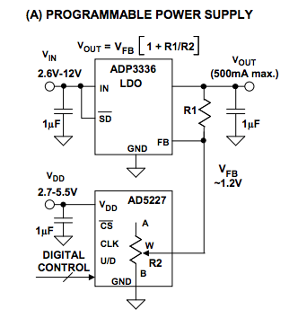
Two more things to do and the first revolves around using a digital pot to control the voltage fed back to the FB pin. Alternatively inject a current into the FB node that can "con" the regulator into assuming a diufferent voltage output. Here's the first idea: -

enter image description here

This was taken from figure 8 in this ADI document.

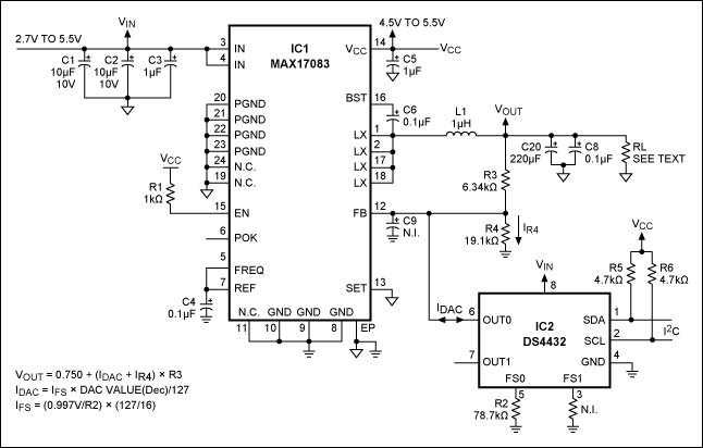
The second idea is to use this type of injection using a current output DAC: -

enter image description here

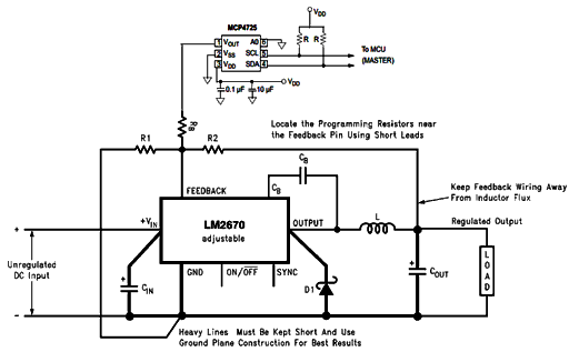
Or like this: -

enter image description here

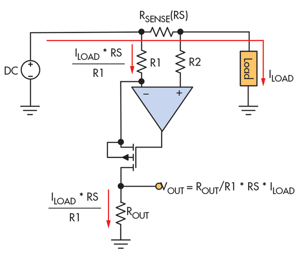
And the second thing to do is have a small resistor in series with the output of the regulator (but before the feedback resistors) that can be used to measure load current. You can use a circuit like this that takes the high-side measurement and references it to 0 volts that can be read by an ADC: -

enter image description here

The above taken from here.

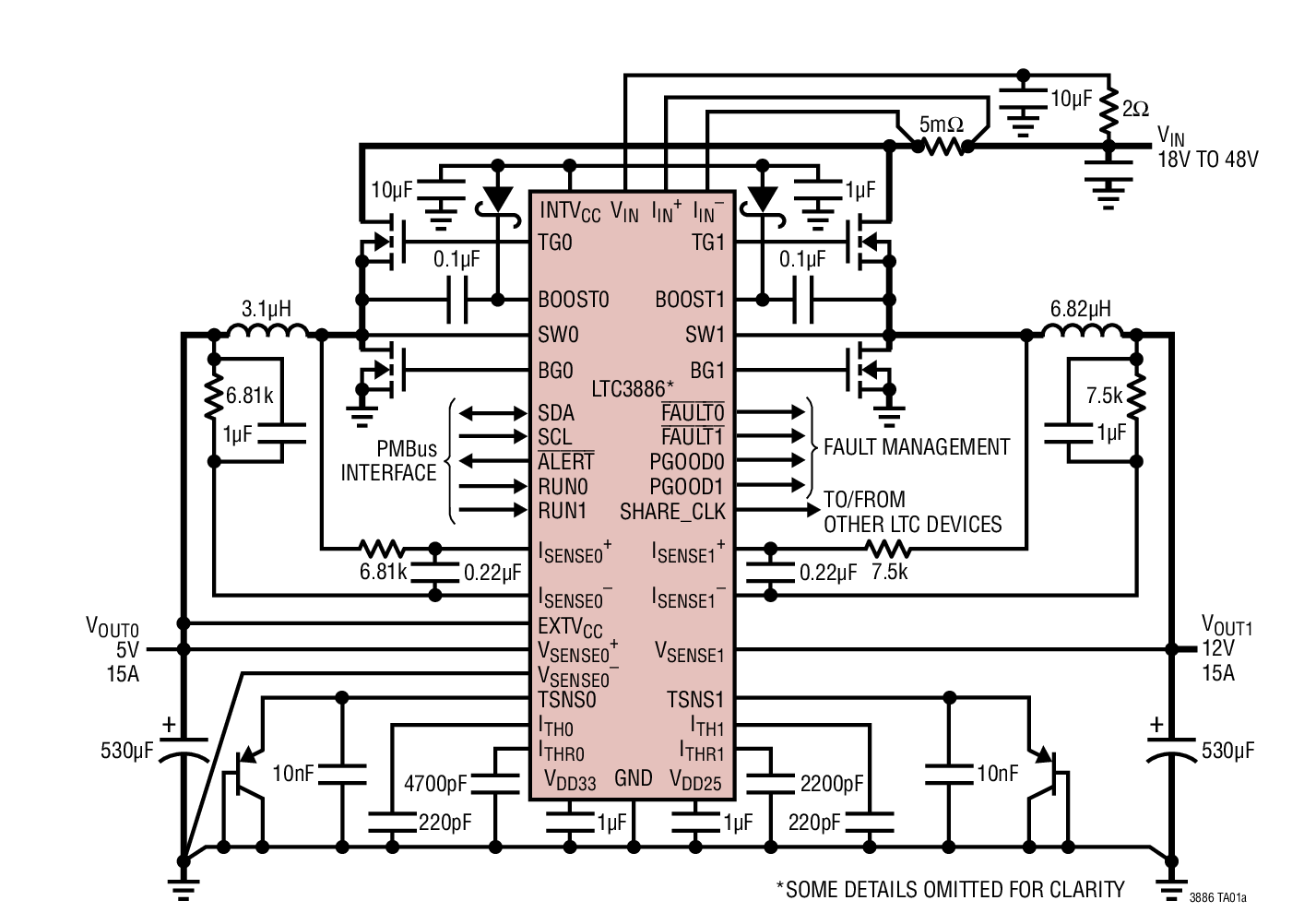
Or you go the whole-hog and get yourself a step-Down controller with Digital Power System Management like the LTC3886: -

enter image description here

\$\endgroup\$
4
  • \$\begingroup\$ Great answer, thanks for the detail. The LTC3886 looks like a very capable chip - it might be the way for me to go. Might even give the capability for more features that I wasn't planning originally. :) \$\endgroup\$ Commented Jul 5, 2017 at 14:26
  • \$\begingroup\$ I think you might only be able to control it down to 0.5 volts so watch out for that. \$\endgroup\$
    – Andy aka
    Commented Jul 5, 2017 at 14:28
  • \$\begingroup\$ @Andyaka - Thanks for the very detailed reply. As I said, im new to electronics but I want to learn and I will try some of this. I think I saw before that you weren't sure where to add the resistance/current control to manage the speed. It looks like it's between the C and T pins. You can see what I mean here when this guy uses a manual speed board for the same type of controller youtu.be/W_Ug0JtW3q8?t=40 \$\endgroup\$
    – Justin
    Commented Jul 5, 2023 at 8:36
  • \$\begingroup\$ @Justin I'm not sure what you refer to when you say this: I think I saw before that you weren't sure where to add the resistance/current control to manage the speed. It looks like it's between the C and T pins <-- so please be more direct. I don't see the relevance of the video link either. \$\endgroup\$
    – Andy aka
    Commented Jul 5, 2023 at 10:21
1
\$\begingroup\$

Something that the other answer doesn't address:

  1. Voltage output with selectable voltage and maximum current (0-12V, 0-10A)
  2. Constant current output with selectable current output (0-10A)

Those are the same thing. The "current only" operation mode means you set the voltage to a maximum value, and the current is regulated.

If you wanted one of those made in a couple of hours:

  1. Buy a 200W car inverter with 120V output.
  2. Buy a 150W 12A/10V switching lab power supply.
  3. Connect #2 into #1, and #1 into the battery.

When it comes to cost, it'd be extremely hard to beat this, unless your time is worth nothing.

If I were to actually design such a supply for personal use - just for the enjoyment of the design process, I'd probably make it a buck-boost switcher with a discrete control loop using op-amps and some gates/analog switches. The programming input would be PWM - to be flexible in the update rate vs. resolution tradeoff. Two duty-cycle-to-voltage converters, each double integrators that alternate hold/charge functions, would convert PWM to reference voltages. Then a current-mode controller as an internal loop, voltage mode controller as the outside loop - nothing super fancy. The switching voltage controller would be set to 1V above the output. A single stage linear regulator would take care of the output voltage. In fixed-current operating mode, it would be in dropout, and that's fine.

There are of course many, many ways of doing this - especially if you would use integrated switching supply controllers.

\$\endgroup\$

Your Answer

By clicking “Post Your Answer”, you agree to our terms of service and acknowledge you have read our privacy policy.

Not the answer you're looking for? Browse other questions tagged or ask your own question.