0
\$\begingroup\$

I am working on a fun side project where I am creating a PWM waveform using the LM324 and a small solar panel. I am using the LM324 for the astable multivibrator, integrator, and comparator. The comparator inputs are the integrated signal (triangle wave) and the voltage level of the solar panel. The generated PWM waveform is outputted to a motor driver (L9110H) that is built into a little fan and motor set up (link)

My PWM generator works great before I plug the PWM output into the input of the driver/motor/fan set up. Before I plug it in I can see the duty cycle change from about 70% to 30% depending on how much light is incident on the solar panel. However when I connect the PWM output of my circuit to the input PWM, it starts acting a little weird. It appears most of the time the PWM duty cycle will not change depending on the solar panel, and sometimes the duty cycle will jump to like 99%. I tried using a unity gain buffer, thinking the motor load was affecting my signal somehow, but that's not really helping. What I expect to see is the fan slowing down when I shade the solar panel, and speed up when it is lit. Any advice or instruction would be most appreciated!

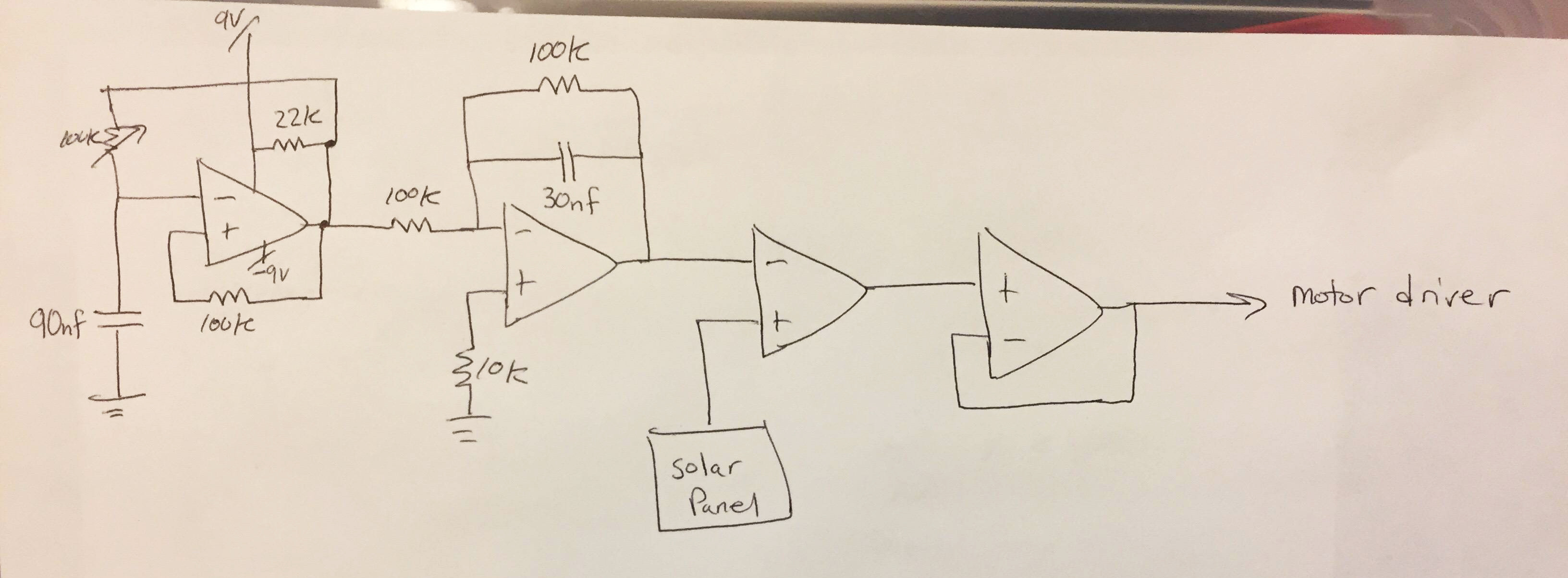
By the way..all op amps have power rails of +/- 9V enter image description here

\$\endgroup\$
6
  • 2
    \$\begingroup\$ We need to see a circuit diagram. \$\endgroup\$
    – MAM
    Commented Jul 9, 2017 at 14:49
  • 1
    \$\begingroup\$ (1) Mark the component types on all the op-amp symbols. It's not clear from your text what is what. (2) Can you crop your photo? Only 40% is actual diagram. There's a built-in schematic tool on the editor toolbar if you require it although your diagram is legible. (3) Many comparitors have open-collector outputs and require a pull-up resistor on the output. \$\endgroup\$
    – Transistor
    Commented Jul 9, 2017 at 15:26
  • \$\begingroup\$ All of the op-amps are the LM324, all in one package. You can't see the entire schematic? \$\endgroup\$
    – Mtk59
    Commented Jul 9, 2017 at 17:58
  • 2
    \$\begingroup\$ You might check for changes in the ground or power rails. The first stage output in this design is sensitive to power supply changes. \$\endgroup\$ Commented Jul 9, 2017 at 22:23
  • 1
    \$\begingroup\$ You need to show the motor driver circuit as well. \$\endgroup\$
    – Glenn W9IQ
    Commented Jul 9, 2017 at 23:00

1 Answer 1

1
\$\begingroup\$

While your schematic does not depict the motor controller portion, if it represents a capacitive load (e.g. a FET gate) to the op amp this will often destabilize the op amp, particularly a unity buffer. Do some web searching for op amps driving capacitive loads, and you willl find plenty of app notes describing how to correct for this with capacitive feedback, etc.

\$\endgroup\$
1
  • \$\begingroup\$ 90% of the time solution: chuck a resistor in series with the output. Not joking, the poles will work their magic. It seems strange to me however that a motor driver could present such a load unless wiring is too long. \$\endgroup\$ Commented Mar 8, 2021 at 7:29

Your Answer

By clicking “Post Your Answer”, you agree to our terms of service and acknowledge you have read our privacy policy.

Not the answer you're looking for? Browse other questions tagged or ask your own question.