2
\$\begingroup\$

I'm calculating the width and spacing for my differential signals to meet impedance requirements.

I have downloaded Saturn Impedance Calculator for making calculations.

My PCB stackup has embedded layers that I want to use for differential signals, looks like the next table:

...
-------------
GND Layer 35um
-------------
Core 180um
-------------
Layer 35um
-------------
Prepeg 176um
-------------
Layer 35um
-------------
Core 180um
-------------
PWR layer 35um
-------------
...

So I have two layers there to place differential signals. Now I'm questioning how should I calculate the impedances. I'm unsure if the reference plane would be the GND and the PWR layers.

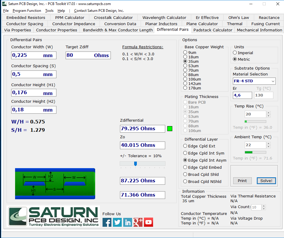
As an example, If I want to meet the 80Ω diff/ 40Ω single impedances, taking the first inner signal layer, and using the Saturn Edge Coupled asymmetric calculator, the input would be:

H2= 180um
H1= 176um
w = 0.225m
s = 2mm

Saturn calc

But I'm unsure if the Height I entered is right, or if I should put the distance to the next reference plane, that is the PWR layer... That distance would be much bigger: 176um + 35um, and would change the impedance.

Anyone know how should I proceed?

\$\endgroup\$

2 Answers 2

1
\$\begingroup\$

The height values you put in are the distances to the surface of the reference copper planes whether they be proper ground or some Vcc plane.

You can check results against on-line calculators such as the one here

\$\endgroup\$
2
  • \$\begingroup\$ Thanks Andy for you answer, so I don't need to add in H1 the distance to the next reference plane. That's my biggest concern... \$\endgroup\$
    – mugurumov
    Commented Jul 10, 2017 at 10:20
  • \$\begingroup\$ I have assumed you do need to add the 35 um because I thought it was FR4. Sorry about that confusion. You take the distance to the surface of the copper plane. \$\endgroup\$
    – Andy aka
    Commented Jul 10, 2017 at 10:22
0
\$\begingroup\$
...
-------------
GND Layer 35um
-------------
Core 180um
-------------
Signals Layer 35um <--- Must be ground pour above the diff pair
-------------
Prepeg 176um
-------------
Signals Layer 35um <--- Diff Pair on this layer
-------------
Core 180um
-------------
PWR layer 35um <-- Must also be ground pour.
-------------
...

H1 and H2 represent the PCB core material only, and as the diagram that Saturn itself shows, they reference the height of that PCB material from the surface of copper to copper.

The copper directly above and below the diff pair must be a ground pour (though the entire layer need not be a pour - just an area sandwiching the diff pair).

So the heights you've entered are correct.

\$\endgroup\$

Your Answer

By clicking “Post Your Answer”, you agree to our terms of service and acknowledge you have read our privacy policy.

Not the answer you're looking for? Browse other questions tagged or ask your own question.