4
\$\begingroup\$

I am designing a product solution which needs a 240V AC to 12V DC. I am getting that done with one of those standard laptop chargers from a reliable OEM(with necessary certifications) which looks like this with a plastic case. 12V Power Supply
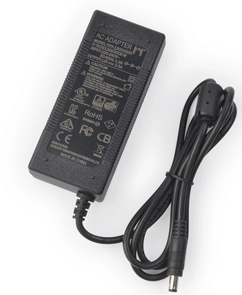
The DC connector from this power supply goes to my device via a mating female DC jack. My device has a painted sheet metal casing. Its not mains earthed as the power supply DC output connector is not having the Earthing pin(Although the AC mains plug has it). After reading about Connecting Chasis GND and PCB Circuit GND here, I am thinking of connecting the Circuit GND with the Chasis via Mounting holes at a few points(I believe most PC Motherboard manufacturers do the same).

  1. Should I be doing the above step as the Chasis is effectively not grounded?
  2. If its connected and there is ESD on the metal chasis, wouldn't the circuit get damaged as its connected to the Circuit GND at multiple points via mounting holes?
\$\endgroup\$

1 Answer 1

4
\$\begingroup\$

Should I be doing the above step as the chassis is effectively not grounded?

Chassis ground is to protect against faults (shorts from power inside of the box to itself) and ESD. With low voltage DC it is not always necessary to protect against faults, with AC mains in a product it is and the mains voltages must be fused.

If there is a fault, it is probably best for the fault current to return through the chassis so grounding the chassis to the ground of the supply is probably the best way to go. In the past I've done this at the input with a DC jack negative terminal connected right to the chassis.

One question I have is what will happen to your DC supply if ESD hits it, it should have certifications that it has been tested for ESD immunity. Again the best pathway is also ground.

If its connected and there is ESD on the metal chasis, wouldn't the circuit get damaged as its connected to the Circuit GND at multiple points via mounting holes?

Electricity always returns to the source via the lowest impedance pathway, so if you shunt the current away from the PCB through the chassis and down the cable that is the best you can do. If you do need to star the ground on the PCB, try and do it as close to the power inlet as possible.

You don't need to connect all of the mounting holes to the PCB ground (you can leave a 10's of mils gap around the mounting hole) just the one by the inlet could be connected to PCB ground (if its a DC jack mounted right to the board). If the PCB has a pigtail, then star the negative terminal on the chassis.

\$\endgroup\$
1
  • \$\begingroup\$ Thanks for the response. So what I am going to do is to connect the negative DC terminal of the power supply to the chasis ground via a single mounting pad as close to the DC PCB mounted jack as possible. \$\endgroup\$
    – dev_000
    Commented Jul 21, 2017 at 6:45

Your Answer

By clicking “Post Your Answer”, you agree to our terms of service and acknowledge you have read our privacy policy.

Not the answer you're looking for? Browse other questions tagged or ask your own question.