2
\$\begingroup\$

So I am looking for a way to switch three signal lines between 1 source and another, the idea being I want to switch a MIDI Port on my device between thru and out modes, but also can't have any delay in the line when in one mode or the other. I have been looking at using some low voltage relays (My device is Arduino Based) as no part of the design is higher than 5v, however I am now looking to see if there is a better solution, specifically, less space consuming (For a pocket device) and that can stand many switches over a long period of time without a potential failure. Any ideas?

EDIT

Hi again, sorry for the confusion. Hopefully this edit will explain it all a bit better.

End Goal

The end goal is for my device to sit in a theatrical show control system and show me the status of the show control system, which will be running MIDI Show Control, basically a specification build on top of MIDI to tell lights, pyro and automation what to do, or what the time into the show is (MIDI Timecode), and the device (Lighting Controller for example) decides what to do. When I press a button, it stops the control system from passing messages to my device so that I can do things separate to the show as a whole.

Control Lines Info

So, when I say three signal lines I mean that in MIDI there are three lines:

  • Positive (The actual signal, +5v or 0v)
  • Negative
  • Shield

When in 'Mode 1', my device will pass all of these lines thru the device onto devices further down the chain. When in 'Mode 2', my device will be the terminating device for those lines and will instead pass a second set of those lines from its self. The idea being that when in 'Mode 2', my device stops signals and can send its own. I have attached a schematic below to show this idea.

Orange arrows are control signals from the original device (Device 1). In Mode 1, these must pass through the device with no delay (I will explain that in a moment), my device will see them but that is all. In Mode 2, these signals stop at my device and I will make new signals to continue onto device 2 (Blue arrows).
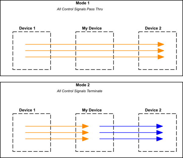
schematic

simulate this circuit – Schematic created using CircuitLab

No Delay

What I mean by no delay is that there can be no real world delay introduced by my device. As this device is part of a show control system, timings are very important. The system may for example trigger two cues, 0.1s apart, so while I understand that electronics add some delay, it needs to be minimal. This is also because the device may be removed (For example, once I have finished programming the show).

Hope this makes a bit more sense than the first post that was a bit rushed.

\$\endgroup\$
4
  • 1
    \$\begingroup\$ Your question could do with some work. (1) You want to switch three signal lines between one source and another. That doesn't make sense. (2) What do you mean by "delay in the line"? (3) Speak slowly. Use paragraphs. Don't do random capitalisation; it confuses the reader. There's a schematic button on the editor toolbar if it helps. \$\endgroup\$
    – Transistor
    Commented Jul 23, 2017 at 20:31
  • 2
    \$\begingroup\$ "No delay" is impossible in this world of physical problems like the speed of light and special relativity. You should research what delay you can actually accept (and I promise, in electronic terms, that will be "quite long"), and then update your question to ask for something physically possible :) \$\endgroup\$ Commented Jul 23, 2017 at 20:31
  • \$\begingroup\$ Also, this question could use a lot more clarity. What about a quick block diagram drawing of what you have in mind? \$\endgroup\$ Commented Jul 23, 2017 at 20:32
  • \$\begingroup\$ Thanks guys, edited the question to try and explain what I mean and what I'm trying to achieve in a bit more detail. \$\endgroup\$
    – Joe Izzard
    Commented Jul 23, 2017 at 21:32

4 Answers 4

1
\$\begingroup\$

Your device already needs MIDI receiver and transmitter circuits when in mode 2. So the simplest way to pass through MIDI signals is to use these existing circuits to implement a MIDI Thru port (as shown in the MIDI specification); the delay of the optocoupler is not noticeable in practice.

To select between the original signal and the processed data from your microprocessor, you can use any SPDT switch, either a digital multiplexer (e.g., the (SN)74LVC1G97), or an analog multiplexer (e.g., the SN74LVC2G53):

MIDI optional Thru with demultiplexer

\$\endgroup\$
1
\$\begingroup\$

Seems to me that a UART at 31250 baud, and an opto isolator is all that is really required. In software when you uart Rx interrupt fires you just copy the byte to the TX buffer, in passthru mode (Latency will be approximately 2/3rds of a ms, not too bad as midi note on takes about a millisecond to transmit (three bytes)), when you want to take over you just talk to the transmit buffer directly.

A more hardware based approach would be an opto isolator or two and a simple mux chip, job done.

I would note that just dumb switching MSC/MMC/MTC/Whatever may or may not work well, it is far better to do at least some parsing and only switch at a message boundary, more code but far, far cleaner. As anything except a relay is in a critical signal path and needs power, you will probably want dual power supplies and (Especially if firing Pyro or Machine control) will want to do the FMEA dance.

\$\endgroup\$
0
\$\begingroup\$

As you may be aware, this site is not a design service. So I will give you some pointers. Feel free to ask follow-up questions.

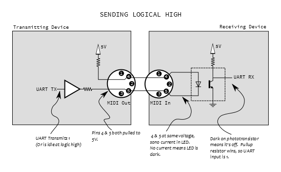
The MIDI signal is a current loop that has complete galvanic isolation between the two devices. The source device provides the current through the two signal wires and this feeds an opto-isolator in the receiver. The source device also provides the shield ground. This shield is not to be connected on the receiving device end. This is to ensure the galvanic isolation remains intact.

You should not think of this project as switching three wires but rather switching the MIDI message.

The common opto isolator in use with MIDI is the 6N138. I recommend you use this device or the 6N139. The MIDI source is normally a 5 volt signal fed through 400-500 ohms of series resistance. This will easily drive the necessary current transfer ratio for any reasonable logic load on the opto isolator.

In order to pass through or repeat the signal to a downstream device, you simply need to create another current loop to the downstream device after the local opto isolator that has converted the current loop from the up stream device to a voltage level based signal. There is no need to worry about delays as this will introduce delays in the order of microseconds, having no effect whatsoever on the MIDI messages.

Your middle device can then be easily configured to pass though the MIDI signal while snooping the messages passing through it or it can intercept up stream messages and send different messages down stream.

\$\endgroup\$
1
  • \$\begingroup\$ Sorry if you felt I was trying to use this site as a system design service because that isn't what I am trying to do. I understand how I want the majority of my device to work, the question is simply what would be a good alternative to an electromechanical relay for this sort of device, as when I research alternatives, I find those relating to AC circuits, and I thought there may be a better solution for low voltage control circuits, to allow me to switch between the two modes. \$\endgroup\$
    – Joe Izzard
    Commented Jul 23, 2017 at 22:46
0
\$\begingroup\$

enter image description here

Figure 1. MIDI cable and interfaces. Source Sparkfun.

The MIDI interface is a glorified LED circuit. Data is transmitted electrically to the receiver opto-isolator LED. The driver and LED form a current loop. Cable shield may be connected at one end but connecting at both ends would cause an earth loop which can introduce hum in audio circuits.

schematic

simulate this circuit – Schematic created using CircuitLab

Figure 2. A double-pole, double-throw switch should do the job.

No batteries, no electronics. Very simple.

Double-check on best practice for shield wiring. It's a long time since I've looked into this.

\$\endgroup\$

Your Answer

By clicking “Post Your Answer”, you agree to our terms of service and acknowledge you have read our privacy policy.

Not the answer you're looking for? Browse other questions tagged or ask your own question.