3
\$\begingroup\$

In a mechanism with strong magnets, I want to use a Hall Effect Sensor to get the position of the magnets. The sensor move between two magnets in inverse polarity, so the field is minimum in on side, Zero in the middle and maximum in the other side.

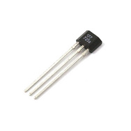
Hall Effect Sensor

Hall effect sensor

Searching on internet, Hall Effect Sensors goes from around -0.07 to + 0.07T, but that is too sensitive and the sensor is saturated most of the time (0V or 5V). (I made tests with the Honeywell SS495A.)

How could I reduce the sensitivity of the Hall Effect Sensor to record stronger magnetic fields?

Note: Because of the design of the device, it is not easy to move the sensor further away of the magnets.

\$\endgroup\$
3
  • \$\begingroup\$ What about the MLX90217LUA-CAA-000-BU? It offers 400mT range instead of 70mT. But I guess you can't use it because it's a switch, not a linear sensor. \$\endgroup\$
    – Reinderien
    Commented Jul 24, 2017 at 20:00
  • 1
    \$\begingroup\$ OK, what about the Infineon TLE4922XANFHALA1 ? 400 mT range, and it's linear. \$\endgroup\$
    – Reinderien
    Commented Jul 24, 2017 at 20:16
  • \$\begingroup\$ You might use a GMR sensor like one from NVE. They make bipolar parts that give you polarity as well as field strength. \$\endgroup\$ Commented Jul 24, 2017 at 23:28

3 Answers 3

5
\$\begingroup\$

How could I reduce the sensitivity of the Hall Effect Sensor to record stronger magnetic fields?

Use a small piece of iron to bridge betweeen the magnet poles - this will reduce the flux density seen by the Hall sensor. It can be placed close to the magnets or close to the sensor. A little bit of experimentation will be required.

\$\endgroup\$
1
  • 1
    \$\begingroup\$ Yes, or even sandwich the sensor between two thin iron sheets, where the plates are wider than the sensor. That will "short out" much of the field seen by the sensor. (Must use iron or even ferrite, since steel adds large nonlinear hysterisis effect.) \$\endgroup\$
    – wbeaty
    Commented Oct 16, 2019 at 1:30
2
\$\begingroup\$

As an alternative idea to shunting the flux, you can try to turn the sensor 90 degrees in the YZ plane, thus vertical to the flux on the middle. This way the sensation pattern will be inverted, the more sparsed middle flux will be the maximum. One glitch is that it will be unipolar, on a memoryless system you can't determine you on which magnet's side are. So, either you will use only half of the distance or if you use MCU, you will computationally track on which side the sensor is.

\$\endgroup\$
2
\$\begingroup\$

Hall sensors "sensitivity" can be adjusted by with a flux concentrator / pre saturation which actually changes the magnetic field the sensor encounters.

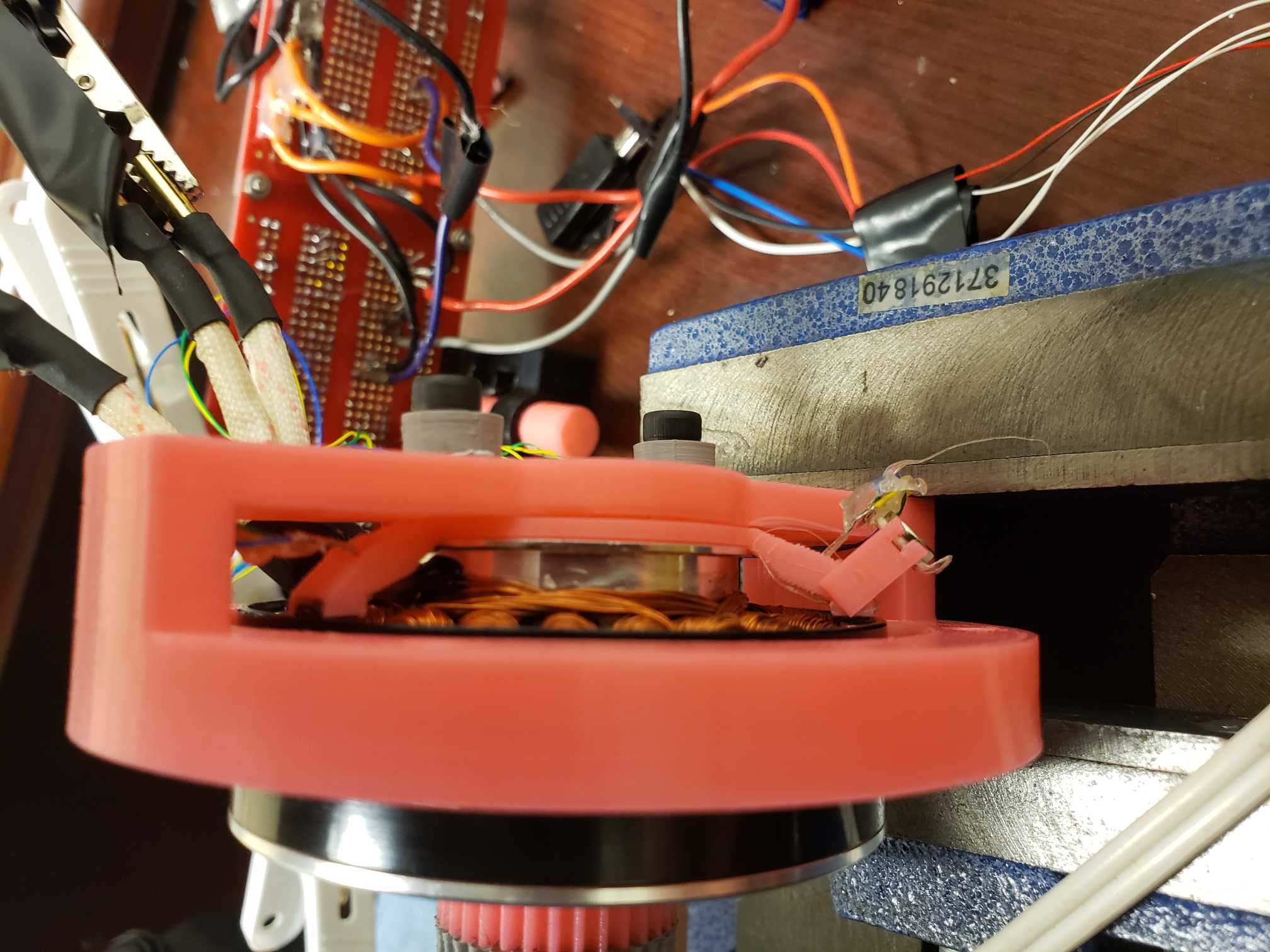
So for example you can use a small neodymium magnet on the backside of your hall sensor. Depending on which way you flip the magnet it will either reduce or increase the hall sensor sensitivity. The distance to the hall sensor will determine the strength of this effect.

Below you can see how the hall senor on the right is now sandwiched between both magnets. The sensor on the left is not done yet. I used a 3d printer to print a custom standoff and it allows me to precisely time my hall sensor sensitivity in a bldc motor.

enter image description here

\$\endgroup\$

Your Answer

By clicking “Post Your Answer”, you agree to our terms of service and acknowledge you have read our privacy policy.

Not the answer you're looking for? Browse other questions tagged or ask your own question.