4
\$\begingroup\$

Some tiny background:

The reflection coefficient, \$Γ\$ can be calculated according to this formula:

$$Γ=\frac{Z_L-Z_S}{Z_L+Z_S}$$

For a transmission line, \$Z_S\$ is the impedance of the transmission line and \$Z_L\$ is the input impedance seen from the transmission line.

If you are using a closed stub on the transmission line, then \$Z_L\$ is 0 which results in \$Γ\$ being -1. A total negative reflection occurs. If you are using an open stub then \$Γ\$ becomes 1. A total reflection occurs.

For a rope, \$Z_S\$ is the impedance of the rope the signal is entering and \$Z_L\$ is the impedance of the other thing connecting it. If you try to whip the rope when the other end of the rope is connected to something fixed, like a building, then the impedance of the wall is 0, \$Γ\$ becomes -1 and you get a total reflection. If you whip and there's nothing connecting the other end of the rope then you get a total reflection. Right, nothing weird.

So the same equations can be used for both waveform mediums.


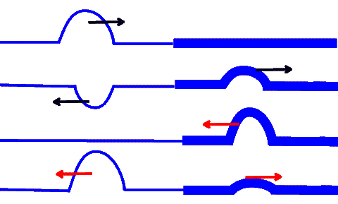
Here's an image of a rope being whipped, at the point where the rope goes from thin to thick, the \$Γ\$ is calculated which describes what should happen to the wave, how much that should be reflected back and how much that should go through.

enter image description here

As you can see with the red arrow, going from a thick medium to a thin medium increases the amplitude, and that's why a whip works, because you hold in the thick end and the whip gets smaller and smaller which makes the amplitude of the wave so much higher and higher, amplified several hundreds of times.

In a transmission line, the same thing happen as in the above image if you got two transmission lines facing each other with different impedances.


Now, here's waldo, if I want to make a physical whip with a rope then I make sure to make the \$Z_S\$ to decrease from my handle to the other end of the rope, or I make \$Z_L\$ larger. Because then the red arrow effect in the image above appears. If I want the same thing to happen with my voltage in a conductor, I should do the same thing. How would that electrical whip look like?

I'm imagining that it would look like some kind of triangle /\ and at the bottom of the /\ triangle you apply some small voltage and at the top you get a massive voltage and possibly some corona appears if I would pulse a 9V battery to it. It would be wound in aluminum foil which would be grounded. Otherwise it's not a transmission line.

Another waldo appears, the reason for why I'm interested in this is because I've never seen any whip effect happen in a conductor, where a voltage grows larger and larger and larger the further it propagates the line. Also I'm a little bit certain that a directional antenna use the whip effect, though I'm not sure at all. And I would use it to turn pulses into ultra tall pulses to see if I can turn on MOSFET's ultra fast, much faster than what they are specified for.


EDIT1

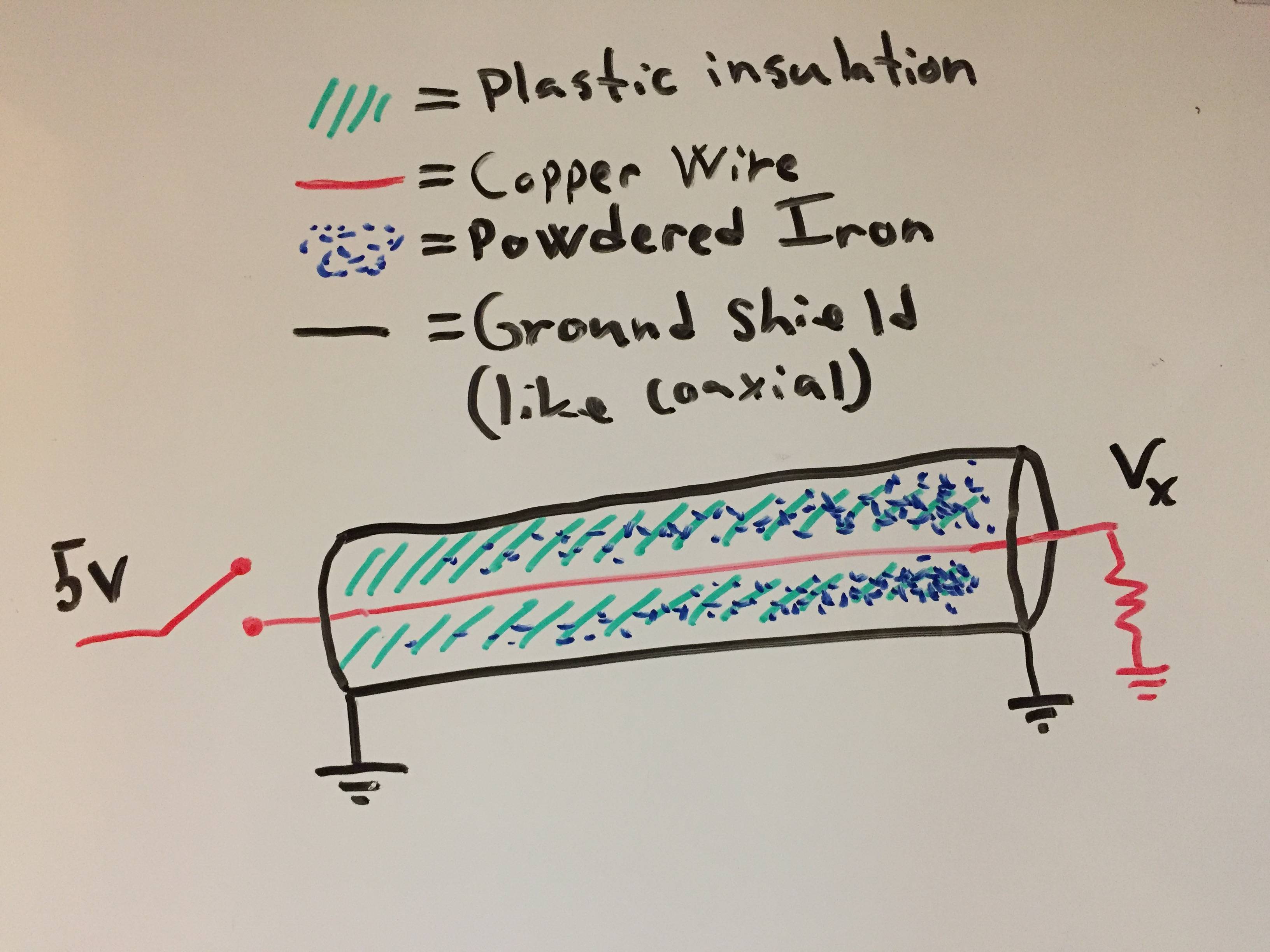
Here's my understanding of how to design an "electrical whip".

electric whip

I assume I need to shield it like a coaxial cable in order for it to act like a transmission line. And if I close the switch for a brief second => send a pulse, then \$V_x\$ should read something much higher than 5V. If it would've been a coaxial cable then it would've been close to 10 volt. Let's just say that the resistance at the end has the value 10k ohm. I'm mismatching the impedances on purpose.

It's a shame that I can't test this out right now.


EDIT2

enter image description here

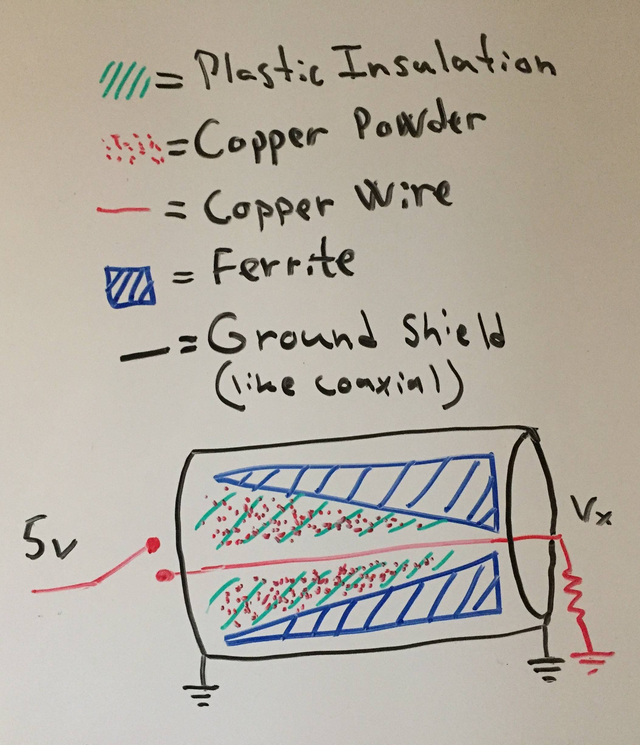
Ferrite doesn't have high permittivity as far as I'm aware. Though it got high permeability
Copper powder got quite high permittivity because of the surface area and distance between the powder is small. Any conducting metal that is not iron or steel can be used as a powder instead for the copper powder I assume. Copper is chosen because of low permeability. The powder must not touch each other.

The electric whip got high permittivity at one end and high permeability at the other end.

\$\endgroup\$
4
  • 2
    \$\begingroup\$ About the edit: Iron powder is highly permittive due the moving electrons in the metal. Altough not conductive because the iron particles are isolated in glue or something, it gets polarized heavily. Think the iron powder as a high C capacitor. You have to find low permittivity high permeability material, maybe some ferrite. \$\endgroup\$
    – user136077
    Commented Jul 27, 2017 at 6:42
  • \$\begingroup\$ Hmm, if I add some copper powder at the start that gradually goes to just iron powder. then there's high permittivity throughout the entire transmission line, but towards the end the permittivity increases. That's enough for an electrical whip effect right? \$\endgroup\$ Commented Jul 27, 2017 at 6:46
  • 1
    \$\begingroup\$ That can work. But now only permeability changes. The maximum effect needs growing permeability and diminishing permittivity as the wave propagates. You should notice that a real mathematician would be needed to solve the wave propagation scientifically acceptably. We have applied the constant parameter model and assumed that gradual change allows the wave to propagate. \$\endgroup\$
    – user136077
    Commented Jul 27, 2017 at 6:57
  • \$\begingroup\$ I assume ferrite instead of iron powder solves everything. And yeah.. the model doesn't really hold.. oh well, at least it's something I want to build and try out. \$\endgroup\$ Commented Jul 27, 2017 at 7:35

3 Answers 3

5
\$\begingroup\$

Your electrical whip = a transmission line where the characteristic impedance grows as the wave propagates. In 2 wire TEM mode lines that means non-parallel wires, the distance between the wires increases along the distance from the signal source.

You have a misunderstanding. It does not make the pulse shorter. The beginning and the end of the pulse need the same time to travel. A whip generates a bang due the incrased transversal velocity which is at the thin end supersonic. That velocity is analoguous with the voltage in the line and it's not the propagation velocity. The motion duration at the banging thin end of a whip is not shorter than the motion duration in the thick end.

You can get the bang also from the electric whip if the voltage exceeds the breakdown voltage of the materials.

In a whip you can increase the transversal velocity easily thousands of percents. In electronic whip the available change is not that radical.It can be made stronger by having also gradually changing isulation between the wires. In the beginning it should be highly permittive, at the end high magnetic permeability is needed.

The electronic whip effect (=the voltage grows as the signal propagates) can be achieved by utilizing an electron beam that travels within the electric signal in the line. Amplification in the travelling wave tubes is the practical result.

\$\endgroup\$
2
  • \$\begingroup\$ "You have a misunderstanding. It does not make the pulse shorter." Ah. of course, you're right. -- "In the beginning it should be highly permittive, at the end high magnetic permeability is needed." So wait a second, does that mean that I change the insulator from a plastic to iron gradually from start to end? (and also shielding the iron from the conductor, obviously) \$\endgroup\$ Commented Jul 27, 2017 at 2:01
  • \$\begingroup\$ @HarrySvensson Gradually changing insulator: Plastic in the beginninng or ceramics = OK. Iron at the end = NOT OK, Its not an insulator. If it is as powder in glue, it is highly permittive. Instead of iron you need high permeability ferrite with low permittivity. \$\endgroup\$
    – user136077
    Commented Jul 27, 2017 at 6:03
3
\$\begingroup\$

Your "electrical whip" was first observed by Nikola Tesla: pancake-coils and conical coils, driven by single pulses and without resonance.

The wide bottom of Tesla's non-resonant cone is the high-current end, while the narrow tip of the coil is the high-voltage end. Or, a more difficult device uses constant-diameter cylinder but graded density of turns, with high turns-per-inch at the high current end, graded to low tpi at the high voltage end. (So, graded iron permeability is more difficult to make. Far easier to just taper the coil diameter, or taper the turns-density.)

Such a device is an impedance translator, "impedance match" or Z-match. It's a single coil with identical effect to a step-up transformer: high-current in, high-voltage out. But in common practice instead we use two-coil transformers, with turns-ratio effect.

Your version is a class of tapered waveguides.

I've seen the conical Z-match used in one place: hobbyist experimental antenna-match (in QST magazine, iirc.) Two wires from a transmitter were connected to the base of two adjacent cone-coils. The tips of the cones were then connected to a dipole antenna with length less than 0.25" wavelength. This has a similar effect as the familiar "base loading" antenna-match device used for electrically-short whip antennas. (Heh, "whip" antenna!) But the tapered-cone device works across a broad frequency spectrum, while base-load has no taper and instead requires resonance: either with variable tuning, or is intended for a narrow range of operating frequency.

Another geometry with similar effect would be a "stripline" transmission line with a tapered triangular section. Wide 3mm stripline on typical epoxy-glass PCB would run at 50ohms and high current, then connect to a tapered section, and the tip of the triangle would merge into very narrow stripline running at perhaps 300ohms and proportionally higher voltage. It's like a transformer, but without any turns-ratio.

One classic antenna uses the tapered-impedance step-up effect: broadband conical antennas, typically used in RF test labs.

In the last couple of years these devices are being advertised in all the RF magazines. They keep the ferrite constant, and vary the coil diameter. The Bias-Tee employs your "whip" effect to achieve broadband lowpass filtering, so that a dc power supply can be connected to an RF transistor output.

Another very familiar geometry is the tapered microwave waveguide, seen everywhere as "horn antennas." The wide end of the horn is matched to the higher impedance of empty space at 377 ohms.

And finally, the tapered bell of any brass wind-instrument is the acoustic analog of your device. Without the horn-shape, the sound wave just bounces back and forth inside the narrow pipe. Add the "horn-match" with its tapered impedance, and this connects the narrow tube to the outside air, preventing the internal reflection, so the high acoustic wattage is able to escape from the narrow pipe.

\$\endgroup\$
2
\$\begingroup\$

How would that electrical whip look like?

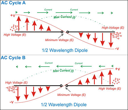
You are describing an EM antenna - it converts a low impedance input to the impedance of free space and, in doing so, can create many thousands of volts at the tip: -

enter image description here

I'm imagining that it would look like some kind of triangle /\ and at the bottom of the /\ triangle you apply some small voltage and at the top you get a massive voltage and possibly some corona appears if I would pulse a 9V battery to it. It would be wound in aluminum foil which would be grounded. Otherwise it's not a transmission line.

Well, maybe that might work (if you applied low voltage at the apex of the triangle), but I imagine one like this: -

enter image description here

You can also make one from a quarter wave monopole.

\$\endgroup\$

Your Answer

By clicking “Post Your Answer”, you agree to our terms of service and acknowledge you have read our privacy policy.

Not the answer you're looking for? Browse other questions tagged or ask your own question.