1
\$\begingroup\$

So I have a simple 2 stage SMPS, boost then buck, using ST's L6563 and L6599. I want to measure the gate drive and other signal components on the ICs. However, whenever I connect the Oscilloscope ground alligator clip to the common ground, my fuse blows. I'm not sure what the problem is, the simplest explanation would of course be that its causing a large inrush current, but I'd like to know how that makes sense, if that is the case. I tested with the oscilloscope powered off and just connecting the pins as well, but same result.

Without the oscilloscope clip, the fuse doesn't blow, but I'm not able to troubleshoot the reason why the 6599 is driving wrongly. Using a multimeter, I can get some voltage values but that isn't entirely helpful. Thank you.

\$\endgroup\$
3
  • 2
    \$\begingroup\$ You have a problem with ground isolation on your boost-buck circuitry; the "common ground" seems to be coupled directly to the hot AC line. A simplified schematic diagram (at block level) will be helpful here. \$\endgroup\$ Commented Jul 31, 2017 at 0:22
  • \$\begingroup\$ @AliChen You're right, there's no ground isolation, my circuit is a variation of the one provided in this application note: st.com/content/ccc/resource/technical/document/application_note/… on page 6. Would it be better if I made a simplified block diagram and showed the points I'm tapping? I'm still not sure why the surge comes though. \$\endgroup\$ Commented Jul 31, 2017 at 0:44
  • 1
    \$\begingroup\$ You can't probe a live AC circuit without some sort of isolation, on one end or another. Your circuit shoud have a polarized plug, with earth ground and neutral close together. Better use an isolation transformer, better on your device end, and make the common ground between the scope and ground of your device under debug. \$\endgroup\$ Commented Jul 31, 2017 at 1:17

1 Answer 1

1
\$\begingroup\$

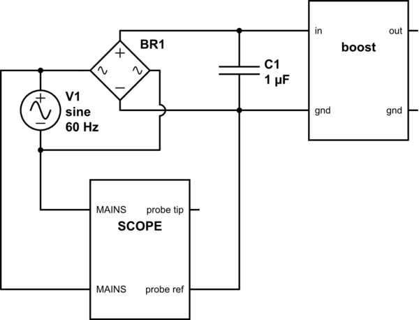
There are some options for you. You probably have a circuit like this:

schematic

simulate this circuit – Schematic created using CircuitLab

Your problem here is that the probe reference of the scope is tied to the mains ground. When you touch the probe reference in the circuit reference/ground, its ground is actually floating between the mains phase and neutral, depending on the time. So, you are connecting the mains phase/neutral to the mains ground and the fuse goes Poof.... It's a short circuit.

There are some scopes with isolated inputs or differential probes witch you could use, but they are expensive.

The best to do would be to use an isolating transformer for your circuit board, between the mains and the board. This way the circuit is protected, you can touch it and not have a discharge, and so is the scope, since it's grounded.

Some mistakes people usually do: They try to float (isolate) the scope. This is dangerous. You will be touching the tips, and the board (witch is not isolated) and you can easily be dealing with 110Vac on the board and touch the reference of another probe and zap!.

Another one is that the two references are connected internally at the scope, so, do not put then in different potentials on the board, otherwise you will damage one (or two) probes. If you are not familiar with scopes, the best would be to remove the reference from one of the probes. You can have more noise on this channel, but you can rest in peace.

\$\endgroup\$

Your Answer

By clicking “Post Your Answer”, you agree to our terms of service and acknowledge you have read our privacy policy.

Not the answer you're looking for? Browse other questions tagged or ask your own question.