5
\$\begingroup\$

I want to power an MCU (ESP8266, 3.3V) and an ultrasonic sensor (HC-SR04, requires >= 3.7V) using AA batteries. By using an efficient LDO (MCP1700T-3302E) and spending much time in deep sleep mode, the average current draw of the MCU itself stays below 0.1 mA. However, since the ultrasonic sensor seems to draw a (relatively high) quiescent current of around 1.5mA, I'd like to control it's VCC line by the ESP and turn it on only when needed. Doing this in a power efficient way seems to be done best using a MOSFET, maybe like in the following schematic?

schematic

simulate this circuit – Schematic created using CircuitLab

Does this plan make sense, what model would be optimal for M1 (especially considering the battery/low power context) and does the gate require an additional pull-down or series resistor?

\$\endgroup\$
6
  • 1
    \$\begingroup\$ If the ESP does not hold its pin state during sleep then you need a pull-down or pull-up (depending on the MOSFET's type) to ensure that the FET is turned off during sleep mode. \$\endgroup\$ Commented Aug 2, 2017 at 10:17
  • 2
    \$\begingroup\$ Milliamps is not a unit of power. Units matter. Fix it. \$\endgroup\$ Commented Aug 2, 2017 at 11:13
  • \$\begingroup\$ @bence: Espressif suggests that the pins keep their state during deep sleep (although current is limited to 2uA). \$\endgroup\$
    – martin
    Commented Aug 3, 2017 at 8:41
  • \$\begingroup\$ i know it's been a long time since you pose this question, i hope you still remember this project because i have a question. why using P-channel MOSFET to turn on the Ultrasonic while you can just use N-channel MOSFET between the ultrasonic and GND (with a pull down resistor) and no need for any BJT. i have a similar project but not with ultrasonic, just a sensor that uses the same power source (between 3.3V and 5V battery not sure yet). \$\endgroup\$
    – shadow
    Commented Mar 29, 2019 at 17:20
  • 1
    \$\begingroup\$ To answer your question, switching ground means that the ground is no longer a true ground and that can cause problems although in this case it might be alright. Please, please capitalise properly to avoid looking semi-literate. \$\endgroup\$
    – Transistor
    Commented Mar 29, 2019 at 17:51

2 Answers 2

8
\$\begingroup\$

Using a P channel MOSFET to switch the power is reasonable, but the way you propose to drive the gate is not.

The microcontroller can drive the gate basically to ground, so turning the FET on is no problem. However, the micro can only drive the gate to 3.3 V, not to its source, so may not turn the FET all the way off. You want the gate to swing the full 0 to 4.5 V range.

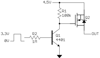
One way to do that is to use another transistor:

When the digital output goes high, Q1 is turned on. That pulls down the gate of Q2 low, turning it on. When the digital output is low, Q1 is held off. R1 then pulls the gate high, turning off Q2.

The turnoff won't be fast (may be a few ms), but that shouldn't matter for the occasional switching the power of the ultrasonic sensor on and off.

R1 was chosen to be so high to minimize the current thru it when the device is powered on. Normally I would have used around 10 kΩ, but in this case that would draw about 30% the power of the device being switched. Making R1 10x larger causes it to use 1/10 the power, or only about 3% of the device current. The downside is that the RC time constant of R1 and the gate capacitance is higher, it will take longer to turn off the FET once Q1 stops pulling the gate low. However, a few ms shouldn't matter in this application as you describe it.

R2 was then simply made R1 x 10. That will draw a tiny amount of current from the digital output, but is enough to turn on any small signal NPN transistor you can find, given that it's collector load is 100 kΩ.

\$\endgroup\$
7
  • \$\begingroup\$ One key to this solution are the values of R1/R2, which are higher than what OP might otherwise find from researching BJT application notes. Those looking to use this solution would be wise to think a bit about why R1 and R2 are the values that they are. \$\endgroup\$
    – scld
    Commented Aug 2, 2017 at 11:29
  • \$\begingroup\$ Is there a special reason for Q1 being a BJT, would be any trouble with a NMOSFET as Q1? \$\endgroup\$ Commented Aug 2, 2017 at 11:31
  • 3
    \$\begingroup\$ @Ben: Q1 could just as well be a N channel MOSFET, so long as it can be turned on well enough with 3.3 V gate drive. Just about any small signal NPN will work here. Those are generally cheaper and more available in junk boxes. \$\endgroup\$ Commented Aug 2, 2017 at 11:36
  • \$\begingroup\$ @OlinLathrop Thanks for your suggestion and the elaborate description. So if I understand correctly, a MOSFET requires a driving voltage (gate) in the range of the voltage to be switched (drain-source). Could the sensor also be switched by a single NPN itself, and if so, what is the advantage of this BJT-MOSFET combination? And (last question :-) are there any suggestions for a concrete MOSFET, or what are important specs to look out for when choosing? \$\endgroup\$
    – martin
    Commented Aug 3, 2017 at 9:01
  • 1
    \$\begingroup\$ @mar: You couldn't use a single NPN to switch the high side power. You could use a single P channel MOSFET if the processor and sensor were running from the same power voltage. \$\endgroup\$ Commented Aug 3, 2017 at 10:55
3
\$\begingroup\$

There may be a problem with gate drive of your high-side MOSfet: ESP8266 cannot pull M1's gate up to 4.5V. This means that M1 may not turn off completely.

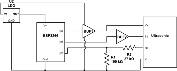
Since your load is low current, you may be able to use a standard high-speed CMOS logic gate as a switch. Use a TTL-compatible gate (HCT rather than HC) to better-match the logic output level of ESP8266. You have many choices, a 74HCT2G34 is an example. In the schematic below, 74HCT2G34's two buffers are "BUF1" and "BUF2". They are both powered from the 4.5 V side of the low-dropout voltage regulator U2. A voltage divider may be advised to convert the 4.5v "ECHO" output of the ultrasonic to a lower logic level compatible with ESP8266. A simple series resistor may be sufficient protection for ESP8266's I/O from over-voltage.
Supply Bypass capacitors omitted only for clarity.

schematic

simulate this circuit – Schematic created using CircuitLab

This solution may be marginal, since the supply voltage spec for HCT logic gates has a minimum of 4.5V, so a low-battery condition should be tested for proper operation.

\$\endgroup\$
2
  • \$\begingroup\$ The voltage divider sounds like a very sensible thing to do, even if the spec (bottom) suggests , that <= 4.5V should be save for the ESP :-)However since my own "empirical studies" showed that the ESP worked stable until battery voltage dropped below 3.6V, I would rather not use components that required 4.5V - why would HC not work in this case? \$\endgroup\$
    – martin
    Commented Aug 3, 2017 at 8:20
  • \$\begingroup\$ @martin - HC would likely work, but HCT has tailored the "high" logic threshold to be more compatible with lower-voltage logic (like your ESP8266) - you get better noise immunity. On the other hand, HC is spec'd down to Vdd=3V. \$\endgroup\$
    – glen_geek
    Commented Aug 3, 2017 at 9:44

Your Answer

By clicking “Post Your Answer”, you agree to our terms of service and acknowledge you have read our privacy policy.

Not the answer you're looking for? Browse other questions tagged or ask your own question.