2
\$\begingroup\$

I am currently interning at a science educational center and for my project, I am creating a simple and educational circuit using batteries, resistors, and light bulbs. The purpose of this circuit is to educate elementary school kids on the concepts of series and parallel circuit. By flipping the switch, they can distinguish the the difference between resistors connected in series and parallel by comparing the brightness.

All 4 resistor values are 1K with 4.5V as input. The specification of the light bulbs are 1.5V @ 0.3A. I have tested all the light bulbs (without resistors) and they are all fully functional. The schematics is shown below. schematics
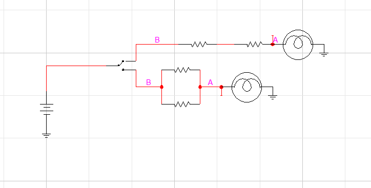
However, the bulbs that are connected to the resistor do not light up. When I used the multimeter measuring from B to point A, it reads 4.5V and when I tried to measure from point A with respect to the ground, it reads 0V.

I know this violates KVL as Vf = VR1 + VR2 + Vb. I cannot figure out why I am getting 4.5V drop through the 2 resistors instead of the 2 resistors plus the bulb. I also tried to up the voltage by using a 9V battery, but the results came back the same. Could it be because the light bulbs are not compatible with resistors?

Thanks in advance.

(Note: My supervisor prefers light bulb over LED even though I tried to convince him to use LED...)

\$\endgroup\$
5
  • \$\begingroup\$ Just in case of series resistors if a current of 0.3A is going to flow through, then you'd get a voltage drop of 0.3*1k=300V across each resistor. That's not going to happen. \$\endgroup\$
    – dirac16
    Commented Aug 3, 2017 at 9:45
  • 2
    \$\begingroup\$ Unfortunately I don't have experience with bulbs and resistors, but I think your resistors are way too high. They would allow only a couple of mA to pass through. Of course that doesn't explain why you measure 0V at node (A): it should be the opposite. But anyways I would try with lower resistors. Assuming you need 300 mA to flow then you would need a \$(4.5V - 1.5V)/0.3=10Ω\$ resistor! \$\endgroup\$
    – nickagian
    Commented Aug 3, 2017 at 9:46
  • 1
    \$\begingroup\$ @nickagian "Of course that doesn't explain why you measure 0V at node (A): it should be the opposite. " - No, it shouldn't. Approximately 0V @ A is entirely expected due to the low resistance of the bulb. \$\endgroup\$
    – marcelm
    Commented Aug 3, 2017 at 12:40
  • \$\begingroup\$ Stick with 4.5V, probably three AA batteries in series. 9V cannot supply enough current, and won't last long. Even so, have a lot of batteries available, because as Olin says, "stuff" happens. \$\endgroup\$
    – glen_geek
    Commented Aug 3, 2017 at 15:01
  • \$\begingroup\$ Your Supervisor is wrong and you are correct. 1K is good for LEDs and no good for a light bulb that is 1.5V/0.3= 5 Ohms hot and probably <<1 Ohm cold so it will never even warm up let alone light. \$\endgroup\$
    – D.A.S.
    Commented Aug 3, 2017 at 21:00

3 Answers 3

2
\$\begingroup\$
the light bulbs are 1.5V @ 0.3A

How do you expect to get 300 mA thru 1 kΩ resistor with only 4.5 V applied? Even with the full 4.5 V across a 1 kΩ resistor, you only get 4.5 mA flowing thru it. With two such resistors in parallel, you get 4.5 mA thru each, so 9 mA total. That's not going to light up a bulb that requires 300 mA for normal brightness. And, this isn't even accounting for the 1.5 V drop across the bulb when it is lit.

One solution is to use lower resistances. Using Ohm's law, we can calculate what they should be. You have 4.5 V available, and the bulb will drop 1.5 V of that when fully lit. That leaves 3.0 V across the resistor. With 3.0 V across it, the resistor should pass 300 mA. (3.0 V)/(300 mA) = 10 Ω. That's the total series resistance for fully lighting the bulb. Since you want that to happen with two resistors in parallel, they should each be 20 Ω.

Also consider the power the resistors will dissipate. Let's be safe and say they need to survive the full 4.5 V applied to them, because stuff inevitably happens. (4.5 V)2/(20 Ω) = 1.0 W. Therefore get "2 W" resistors. Those are also larger and easier to see, so better for demonstration purposes anyway.

\$\endgroup\$
0
2
\$\begingroup\$

Your light bulbs are specified as 1.5v, 0.3A. This means their resistance when hot is 5ohms (1.5/0.3). When cold, the resistance will be around 1/10th of that, say less than 1ohm.

Comparing 1kohm to 1ohm, you can see that essentially all of your battery voltage will be dropped across the 1k resistors, with very little across the bulbs.

To put it another way, a bulb needs at least half its rated current in order to glow visibly, so 150mA for those bulbs. With 4.5v available, 1k resistors limit the current to a few mA, not enough to have a visible effect on the bulb.

To get 150mA with 4.5v, use resistors no larger than 4.5/0.15 = 30 ohms. Also make sure your power source can supply that current.

OTOH, LEDs might be better as they light with much lower currents. OTOH, LEDs are always the same colour, and it can be difficult to perceive even as much as a 2x difference in brightness as a result of current. A filament bulb, especially when being run well below its rating, changes colour as well as brightness, and will be much better indicator for differences in supply current.

\$\endgroup\$
0
\$\begingroup\$

I'm going to take a different track for you to consider based upon what you wrote that resonated with my thinking:

  1. Use incandescent light bulbs spec'd at \$1.5\:\textrm{V}\$ and \$300\:\textrm{mA}\$.
  2. Vary the brightness in a way that clearly illustrates parallel vs series resistance using these light bulbs.
  3. Work with a voltage source of \$4.5\:\textrm{V}\$, supplied via three standard \$1.5\:\textrm{V}\$ batteries.
  4. I don't feel constrained by your writing to not add another part, so I feel you are open to anything that makes this work well for a demonstration.

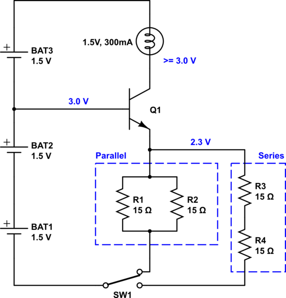
Consider the following schematic:

schematic

simulate this circuit – Schematic created using CircuitLab

You can hide some of the details in the demonstration, if that's important to you.

The resistors should probably all be \$1\:\textrm{W}\$ just to be safe. Dissipation will be a lot less (perhaps a third as much or less), so you might be able to get away with less. But this is a demonstration and it is probably better to keep the temperatures relatively modest.

The BJT will only need to dissipate perhaps \$250\:\textrm{mW}\$, but again it's probably better to use something in a TO-220 package to keep it totally cool and safe. I'd recommend a D44H11 here. They are cheap and quite capable and readily available. If you re-arrange the circuit to use a PNP instead (for whatever reason) you could use the D45H11, instead. In fact, you can figure out which of those two are easier to get (or any other TO-220 or TO-3 packaged unit) and just base the circuit on what is easy to get.

(The light itself is going to dissipate about half a watt. So be aware of the possibility of that getting warm in the demonstration.)

The BJT operates in "emitter-follower" mode and the arrangement pretty much guarantees that the resistance (parallel or series) determines the current in the light bulb. The BJT regulates things to make sure that happens well. So it's pretty solid in terms of making things work with a simple battery system without all the gnashing of teeth and wringing of hands regarding the simpler circuit topology you were attempting to use.

Of course, there is the possible problem that it isn't simple enough. But I thought I'd offer it, just in case. It only adds one component. Which buys you a lot, I think. But it is up to you, of course.

\$\endgroup\$

Your Answer

By clicking “Post Your Answer”, you agree to our terms of service and acknowledge you have read our privacy policy.

Not the answer you're looking for? Browse other questions tagged or ask your own question.