1
\$\begingroup\$

I designed and breadboarded a simple audio amplifier circuit and when I play audio through the speaker, it is pretty noisy and very quiet. The +5V is being supplied from a USB port.

I'm still probing and testing different spots, so I'll try to update with some scope shots and real measurements besides "it sounds quiet and noisy", but in the meantime, does anyone see any design flaws?

I'm thinking that I may not being supplying enough current and I've noticed that the inverted signal on the output of the second op amp seems to have a clipped voltage swing, about 1V less than the voltage swing on the output of the first op amp.

And as I've been typing, I'm wondering if I should tie the output of my push-pull outputs back to the op amps.

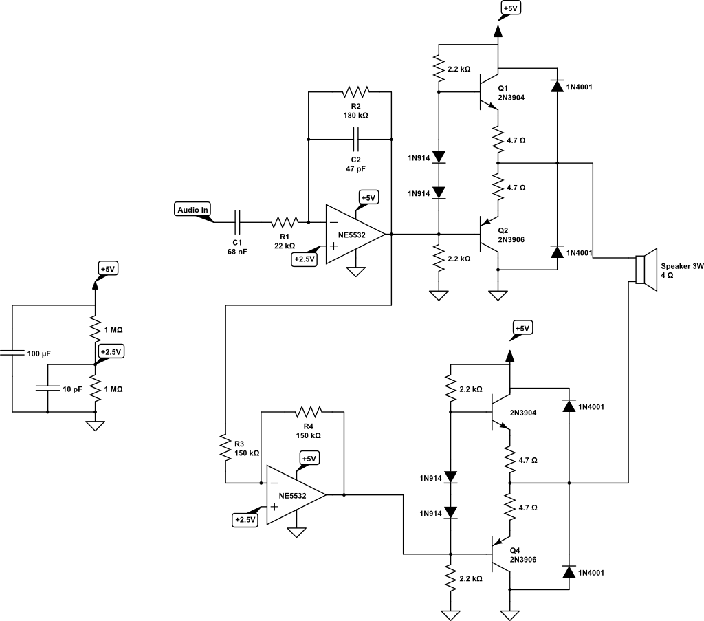
Thanks BTL push-pull output, had a typo on diode polarity

\$\endgroup\$
1
  • 1
    \$\begingroup\$ The datasheet for the 5532, when running from +/-15v rails has a peak to peak swing of ~26 volts, that is it can't get to within 2 volts of either rail. Running it at 5v and biasing it at 2.5 doesn't give you much headroom, especially considering the Vbe of the emitter followers. \$\endgroup\$
    – Colin
    Commented Aug 4, 2017 at 7:19

3 Answers 3

1
\$\begingroup\$

The first thing that struck me, starting looking from the left, that made no sense to me is your \$2.5\:\textrm{V}\$ reference. Why only \$10\:\textrm{pF}\$? Why \$1\:\textrm{M}\Omega\$ resistors?? It just doesn't make sense on its face.

Then I started looking at what the inputs of the opamps "see," looking backwards. And it's not even close to balanced, for either of them.

Then I saw the resistors and diodes as your "current source" for driving the output BJTs and knew that would be a problem. Then I wondered if the NE5532 could even hope to drive that thing, bad as it already was....

And then I saw the output diodes and nothing else mattered anymore.

Take a look at the polarity of the diodes tied across the resistor+emitter to collector of both \$Q_2\$ and \$Q_4\$.

Do you see any problem there?


EDIT: Okay. So that problem is really just a "typo" in your schematic.

Let's start at the beginning. You are going to all this trouble with a BTL topology and for all your trouble you intend on running this with only a \$5\:\textrm{V}\$ supply rail? Is that true? Or are you flexible there? What kind of output wattage do you expect to deliver into the \$4\:\Omega\$, \$3\:\textrm{W}\$ speaker? Explain your thoughts about your half-rail reference voltage design? (And yes, you will probably need feedback.)

\$\endgroup\$
3
  • \$\begingroup\$ Oh whoops, I drew the circuit wrong with the polarity of the diodes. Thanks \$\endgroup\$
    – lemonlime
    Commented Aug 4, 2017 at 4:27
  • \$\begingroup\$ Yes, sorry, I should have specified. I'm being constrained to only having a +5V rail from a USB port. I figured I would bias my audio signal to the half-rail reference so I could amplify and preserve the downswing of any audio signal and then use BTL topology to try and squeeze out some extra power. I was hoping to get about 2W into the load. \$\endgroup\$
    – lemonlime
    Commented Aug 4, 2017 at 5:56
  • \$\begingroup\$ @user157825 That's \$2\sqrt{2\cdot P \cdot R}\approx 8\:\textrm{V}_\textrm{PP}\$. You included huge emitter resistors. But even if you removed them and used a bridge-tied load arrangement, you still must account for emitter swing limits and other drops. My guess is that you cannot expect to do better than about \$4\:\textrm{V}_\textrm{PP}\$ with your rail, taking into account necessary headroom. That's \$\frac{1}{2}\:\textrm{W}\$. If you are serious about this, I'd just pop in a TDA8551 (I have hundreds of them) and be done with it. Those top out at \$1\:\textrm{W}\$. Can you do better? \$\endgroup\$
    – jonk
    Commented Aug 4, 2017 at 6:09
0
\$\begingroup\$

Yes you should tie the outputs of the pushpulls to the opamps.

\$\endgroup\$
0
\$\begingroup\$

From the NE5532 datasheet:

enter image description here

You will have to use a different opamp or a higher supply voltage of at least +-5V (10V single supply).

\$\endgroup\$

Your Answer

By clicking “Post Your Answer”, you agree to our terms of service and acknowledge you have read our privacy policy.

Not the answer you're looking for? Browse other questions tagged or ask your own question.