1
\$\begingroup\$

I am a bit confused about this differential base-emitter resistance.

I has been said that r_pi doesn't have much influence on small signal input impedance, when CE with emitter degeneration is used. Well, I doubt this claim.

Can someone please explains why or when should r_pi be neglected in small signal input resistance calculus for CE with emitter degeneration?

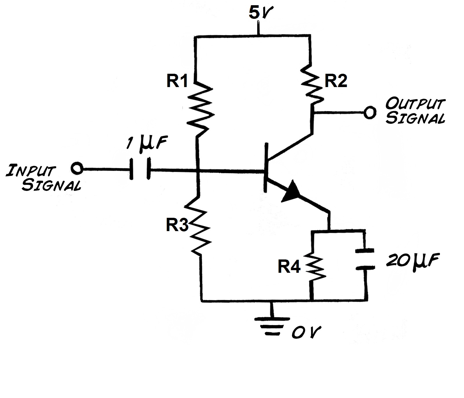
enter image description here

\$\endgroup\$
11
  • \$\begingroup\$ The emitter resistor is NOT "most probably bypassed by capacitor" at all and this claim is putting me off answering because it seems you have things muddled up. I'm not sure what your question is based on your false claim. \$\endgroup\$
    – Andy aka
    Commented Aug 7, 2017 at 7:16
  • \$\begingroup\$ @Andyaka But how? Capacitor to ground from emitter lead equals as grounded emitter for small signal analysis, right? Why else would emitter resistor be bypassed. And I didn't muddled up anything... \$\endgroup\$
    – lucenzo97
    Commented Aug 7, 2017 at 8:25
  • \$\begingroup\$ You say that "Emitter resistor will be most probably bypassed by capacitor" and this is just not true. Then you say "so emitter can't really have much influence on small signal input impedance" and this is also not true. Your claims and your questions are not obviously separated enough to make an answer. Clean up your question and don't make false assertions. \$\endgroup\$
    – Andy aka
    Commented Aug 7, 2017 at 9:04
  • \$\begingroup\$ @Andyaka Edited. \$\endgroup\$
    – lucenzo97
    Commented Aug 7, 2017 at 9:10
  • 1
    \$\begingroup\$ Rin = R1||R2||r_pi (with CE across RE or without RE at all) The input resistance with RE and without CE capacitor is Rin = R1||R2||(r_pi + (beta+1)*RE) \$\endgroup\$
    – G36
    Commented Aug 7, 2017 at 12:35

1 Answer 1

1
\$\begingroup\$

There are TWO high-pass filters in that circuit.

The input cap is one.

The emitter-resistor-bypass is the other.

Both of these capacitors cause a rising output signal level.

Thus 12 db/octave or 40dB/decade.

Its your job to manage the timeconstants of these TWO HPF.


What is the input impedance?

Zin is Z(c1) + the parallel combination of

a) R1

b) R2

c) Miller Capacitance [stage voltage gain * Cob (C collecter to base) ]

d) the sum of beta* [1/gm + { R4 in parallel with Z(20uF) } ], where beta*1/gm is R_pi.

\$\endgroup\$
3
  • \$\begingroup\$ Ok. But that stil doesn't explain the meaning of r_pi, or when should it be neglected and when not. \$\endgroup\$
    – lucenzo97
    Commented Aug 8, 2017 at 7:40
  • \$\begingroup\$ Part d) of your answer is NOT correct. You forgot the effect of negative feedback, \$\endgroup\$
    – LvW
    Commented Aug 9, 2017 at 11:36
  • \$\begingroup\$ @ LvW You are correct. 'd' should be beta * { 1/gm + (R4 in parallel with Z(20uF)}. Edited the answer. Thanks. \$\endgroup\$ Commented Aug 10, 2017 at 4:59

Your Answer

By clicking “Post Your Answer”, you agree to our terms of service and acknowledge you have read our privacy policy.

Not the answer you're looking for? Browse other questions tagged or ask your own question.