4
\$\begingroup\$

Is there a way to regulate max DC voltage on a circuit when the input voltage CAN exceed the desired voltage?

I'm trying to figure out power supply/regulation for a fan where the datasheet specs for 10.8v to 13.2v input at up to 4.6A. I have bench tested the fan up to 14.1v and it didn't fail, so there is some margin of error above 13.2v.

However, my input voltage can vary from ~11.5v to 15.2v. Normal operating range is ~12-14v. Total draw for the fans is ~9.2 amps (2 fans).

I have looked at the following:

1) LDO regulators - generally can't supply enough power (even if divided into two circuits, one for each fan), plus I'd have to set for a low voltage to begin with (~11v) which would wind up wasting a fair amount of power most of the time.

2) Avalanche diodes - This could sink significant amounts of current, which would be bad.. not just for the PCB but also because of the battery chemistry it is drawing from as it would pose a fire risk.

3) Switch mode regulators - generally speaking you need some margin above your target output voltage, which isn't always the case here..

4) Using a power diode in series to drop the voltage some arbitrary amount and just heat sink away the wasted power. Inefficient but may work. The problem is I would need it to sink ~1v at the top end of the voltage range and less than that at the bottom (preferably closer to 0.5v) which doesn't really seem possible in the datasheets I've been looking at.

So far #4 looks like the best of the "not good" options.. But are there any options I'm missing here?

\$\endgroup\$

6 Answers 6

8
\$\begingroup\$

Switching regulators can go both ways

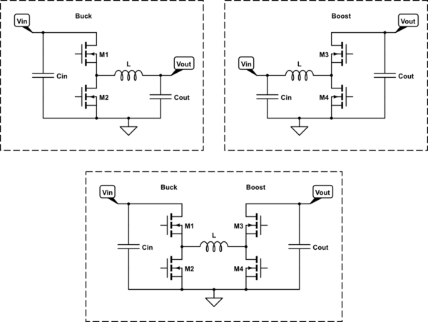
Switching regulators can not only step down the voltage (as in a buck converter), but can step up the voltage (a boost converter), or even regulate a voltage that may be above or below the output (you'd use either a four-switch buck-boost or a SEPIC converter for this). (They can also invert the polarity of an input, but that's neither here nor there.)

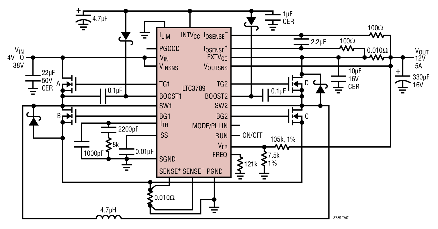
Unfortunately, 9.2A is rather outside the range of a SEPIC as the SEPIC topology is capacitively coupled and you can't really get capacitors that can handle 9.2A of high frequency ripple current without heating up a bunch and causing other problems. This leaves the four-switch topology as your primary option. Furthermore, you'll need to use a controller and external power FETs at such high currents, as in the LTC3789 circuit depicted below:

LTC3789 demo circuit

\$\endgroup\$
5
\$\begingroup\$

You missed PWM (pulse-width modulation). Use a big transistor / MOSFET to pulse the motor at a duty cycle appropriate to give the required average current to the motor. e.g. Give 100% on-time up to 12 V falling to 80% at 15 V.

Pay attention to adequate fly-back protection diodes. These need to be capable of handling the full rated current of the fan.

\$\endgroup\$
2
  • \$\begingroup\$ This is a good idea, unfortunately I didn't mention in my original post that the PWM control circuitry is already built into the fan and a PWM signal is provided to the fan on a separate lead. So I think the voltage spec is not only for the fan itself but also the on-board control circuitry. \$\endgroup\$
    – Ray Ackley
    Commented Aug 19, 2017 at 15:58
  • 1
    \$\begingroup\$ Agreed. You didn't mention that. \$\endgroup\$
    – Transistor
    Commented Aug 19, 2017 at 17:04
5
\$\begingroup\$

ThreePhaseEel has the correct answer, as already noted, but I'd like to redraw the schematic for my own understanding and to highlight the important parts. Maybe it'll help someone else too.

schematic

simulate this circuit – Schematic created using CircuitLab

So a Four-Switch Buck-Boost really is one followed by the other, at least as drawn in TPE's example. The rest of the components are for current and voltage feedback in various places or to adjust the controller's logic.

To simplify the control at the expense of some efficiency, M2 and M3 could be replaced with diodes. (both "pointing up") These are actually included parasitically in all the FETs (M1-M4), meaning that a manufacturer can't get rid of them even if they wanted to, so every symbol like that should be imagined with an "ordinary" silicon PN diode across it. The app note puts a couple of schottky diodes there anyway because their lower voltage drop results in less power loss if they ever were to conduct. (but still not nearly as good as their respective FETs being on)

\$\endgroup\$
3
\$\begingroup\$

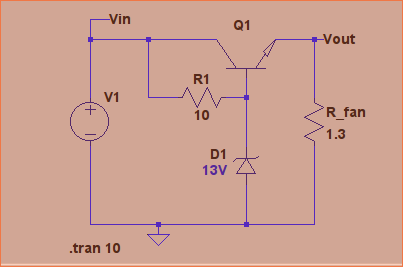
One other possibility would be a crude linear regulator such as:

Circuit

The output voltage varies with input voltage something like:

Output

\$\endgroup\$
2
  • 1
    \$\begingroup\$ Q1 is going to need to be pretty hefty to make this work. At Vin = 15.2v it's going to be dropping about 2.8v at 9.5A => it needs to dissipate 26.6W. I'm not sure what you'd use for this, but my usual supplier doesn't have anything that matches (although they do have the NTE2547 which comes close... perhaps using one for each fan might work). \$\endgroup\$
    – Jules
    Commented Aug 19, 2017 at 22:18
  • \$\begingroup\$ @Jules You could always stick the transistor in front of one of the 50-watt fans to cool it. \$\endgroup\$ Commented Aug 20, 2017 at 5:12
0
\$\begingroup\$

The buck-boost converter is valid, but it looks like it wil more than double the price of the cooling fan assembly and slash the MTBF (mean time between failures) to a small fraction of the fan motor life.

The most obvious first step is to stop solving a problem the customer may not need you to solve. I don't recognize your particular power bus specs, but they look like someone is adding safety margins to a typical vehicle 12v lead acid battery power bus. 11v represents engine off or alternator failed with depleted battery and some copper loss and a polysilicon fuse at full load. The 15.2v represents engine-on, failed voltage regulator, overcharged and sulfated battery, lightly loaded power bus. If some of this range can be pushed into a survive for 100 hours instead of normal operating conditions, you may all save some money, but sometimes the path to the system or platform's chief engineer is too long and the specs can't be sanitized.

The second most obvious solution is to contact some fan vendors. You aren't the first person to need a bigger voltage range. Military platforms are typically much larger ranges. The fan vendors have a lot more fan motor design variations and blade/wheel designs available than they catalog. Keeping the number of variations down improves volumes and pricing, and distributor shelf space so expect to pay more for an uncommon motor and or blade/wheel, but at least it won't tank your MTBF at the same time. The best part about this solution is that at most companies the purchasing department will want to take the lead and will take care of finding vendors and stirring up options and only involve you to confirm details and a final list of acceptable choices. They'll handle all the phone calls and the boilerplate and keep the tree of options being explored for management and do the cost/volume haggling and all the vendor salesmen will still invite you along for the free lunch at the nice restaurant. Minimum extra work, someone else has to put together the status and explain it to management, and free lunches. Think about it.

Only increase system complexity and cost when there's no other option. In this case there are at least 3 choices for increasing fan voltage range using off the shelf fan motors with a narrow voltage range.

1) Use a PWM chopper to cut the peak RMS voltage, let it go to 100% except when necessary. PLUS: minimum complexity and design effort, uses motor magnetics for reactive smoothing. MINUS: no low voltage boost, large airflow variation Vmin to Vmax, need to qualify motors for compatibility with chosen PWM scheme, unknown EMI mitigation cost risk.

2) Use a boost regulator and change to a higher voltage motor. PLUS: constant motor voltage minimizes airflow variation, limited EMI mitigation cost risk. MINUS: higher cost, needs cooling, needs stalled (stuck) motor protection, adds significant FITs (failures in thousand hours), have to change fan motor selection.

3) Use a buck regulator and change to a lower voltage motor. The PWM input to the 12v motor could be considered a variation on this scheme. A full-up isolated buck converter isn't needed and isn't cost effective. Cost effective versions will use a chopper and the motor reactance and as little else as possible, which suggests a nominal motor voltage near Vmin. PLUS: Low cost, minimum added complexity, low airflow variation MINUS: adds FITS and $, changes motor, must qualify motors compatible with PWM scheme chosen, unknown EMI mitigation cost risk.

Note that all of the motor control schemes have to be roust enough to support the stalled stalled rotor current to start the motor, not just the average running current, but you can make complexity trade offs about the short term start load versus the stuck rotor overheat and burn issues.

If the voltage range has to be supported, a motor that will accomodate it with appropriate overheat protection is certain to be the high MTBF choice and lowest NRE (nonrecurring engineering cost) and its extremely likely to be lowest unit cost as well.

\$\endgroup\$
0
\$\begingroup\$

Didn't see the mini-note where the OP mentions it's a thermal control fan. There's no inherent reason for the built-in brushless motor control to be limited to a tiny voltage range, but Vmax does set peak transient voltages and a lower value lets them buy lower voltage parts. If the vendor can't offer improved specs ask another vendor. A simple fan and a separate thermal control PWM will be more trouble and cost more than buying a fan with what you want, but if you can't find what you want it's an option. Pasting on a complex voltage regulator to overcome an ill suited thermal feedback motor control shouldn't be necessary.

\$\endgroup\$

Your Answer

By clicking “Post Your Answer”, you agree to our terms of service and acknowledge you have read our privacy policy.

Not the answer you're looking for? Browse other questions tagged or ask your own question.