0
\$\begingroup\$

I am using the ADC of the PIC16F18344 —

http://www.microchip.com/wwwproducts/en/PIC16F18344

It has neither Avdd nor Agnd, but it does have selectable Vref+ and Vref- pins. If I were to stop using chip Vdd and Vss for ADC, dedicate a regulator to Avdd and Avss, run these lines to the Vref pins, and select them in the firmware, would I see accuracy benefits equivalent to a device that had dedicated analogue supply pins? I think, for this application, noise immunity is more important than absolute accuracy. There is also calibration supported, as well.

Currently the ADC is connected in simple voltage divider/"ratiometric" configuration with a rheostat:
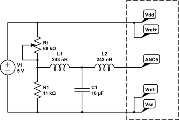
schematic

simulate this circuit – Schematic created using CircuitLab

I am using all 10 bits of the result, although I can tolerate some error in the least-significant bits. I am using a software median filter to cancel noise and it works fairly well. The sampling rate is quite low, perhaps two or three times a second. There is a passive T filter before the ADC; the chokes are actually approximations of ferrite cores.

\$\endgroup\$
6
  • 1
    \$\begingroup\$ What does the data sheet tell you about the accuracy of conversion with respect to type of voltage reference? \$\endgroup\$
    – Andy aka
    Commented Aug 25, 2017 at 14:15
  • 1
    \$\begingroup\$ A MCU with both analog and logic / memory / outputdriver / clocking on a single VDD and single GND pin will always trash the ADC unless the MCU program execution is shut off during ADC sample/hold and binary-search-conversion. Why? The PSRR --- power supply rejection ratio --- of the ADC will be poor at high frequencies (the transient edges of change demands during program execution). A clean VREF does not improve the PSRR. What #bits do you need? Expect 0.5 volts internal upset of the VDD/GND rails. If Vref is 2.5v, you have 5:1 ratio of 2.5/0.5, or 2 bits ADC performance. \$\endgroup\$ Commented Aug 25, 2017 at 14:20
  • 1
    \$\begingroup\$ You should also clarify if you're looking for absolute accuracy or if you're looking for low noise. There's a big difference. The dedicated analog supply pins help with noise issues. Absolute accuracy is more dictated by how good the voltage reference is and how good the ADC is in terms of INL specs. You can reduce the noise with averaging. You can improve accuracy by calibrating, though you'd still have to deal with temperature coefficients and long term drift. \$\endgroup\$ Commented Aug 25, 2017 at 16:51
  • \$\begingroup\$ @analogsystemsrf I use all of the bits available, although I can tolerate some error in the least significant bits. Vref+ will be 5V, the same as Vdd, and Vref- will be 0V, the same as Vss. \$\endgroup\$
    – Reinderien
    Commented Aug 26, 2017 at 17:53
  • 1
    \$\begingroup\$ @Reinderien, there's no right or wrong; just right or wrong for what you're trying to achieve. If you only need a measurement that needs 5% absolute accuracy, then by all means use VDD to cut cost. Or maybe absolute accuracy isn't that big a deal but you're using the ADC for signal processing and detecting a signal then maybe you just use an RC divider and big capacitor to low pass filter VREF+. You should clearly define what your problem is (ADC, resolution, absolute accuracy, noise, sampling rate, etc) before you go look for a solution. \$\endgroup\$ Commented Aug 26, 2017 at 20:03

1 Answer 1

1
\$\begingroup\$

would I see accuracy benefits equivalent to a device that had dedicated analogue supply pins?

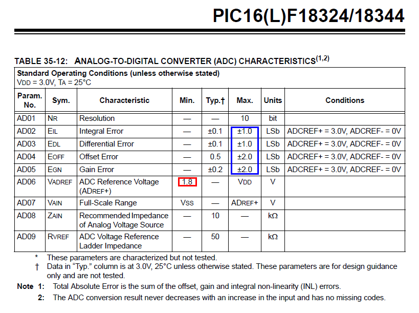
Well, the data sheet isn't that great. For instance it doesn't obviously tell you what would be the accuracies if you used the software selectable internal voltage reference so, ignoring that and basing my answer stricly on the question asked, the table on page 425 provides some insight: -

enter image description here

The basic accuracies are shown within the blue box and could be up to +/-6 LSBs. With a voltage reference of 3 volts (Vdd = 3) one LSb is 2.93 mV and so a reading could be accurate to +/- 17.6 mV.

If your input signal is such that it needs to use most of 3 volt span then you are stuck with an accuracy of +/- 17.6 mV. However, if your input signal might only range between 0 volts and 1.8 volts then one LSb is now 1.76 mV and you have an accuracy of 10.6 mV.

Generally it's better to use an external reference but, if that voltage reference is 3 volts then expect no improvement other than that due to it being stabler that the voltage regulator that produces Vdd.

However, if you are measuring a signal that is ratioed to Vdd then use Vdd as the reference because then you get the benefit of a ratiometric conversion (if needed).

\$\endgroup\$
3
  • \$\begingroup\$ Its not at all clear on this data sheet just how far Vref- can stray from Vss before bad things happen to ADC linearity. Seems that Microchip test with Vref- = Vss. Also, why not add a few SAR cycles to boast 12-bit ADC when integral Error is typical +/-0.1 lsb? \$\endgroup\$
    – glen_geek
    Commented Aug 25, 2017 at 16:23
  • \$\begingroup\$ @glen_geek it's really poor but I would say that they would be lying if they can't maintain the LSb errors as they are shown down to a Vref of 1.8 volts. Gloves off below that. \$\endgroup\$
    – Andy aka
    Commented Aug 25, 2017 at 16:49
  • \$\begingroup\$ @Andyaka I think that "ratiometric conversion" is what I'm already doing. The input is from the middle of a simple voltage divider with a thermistor and a high-accuracy, low-temperature-coefficient resistor. Currently the top and bottom of the divider share the same supply as the supply to the uC. \$\endgroup\$
    – Reinderien
    Commented Aug 26, 2017 at 17:58

Your Answer

By clicking “Post Your Answer”, you agree to our terms of service and acknowledge you have read our privacy policy.

Not the answer you're looking for? Browse other questions tagged or ask your own question.