2
\$\begingroup\$

I need to measure the energy usage of a small bluetooth device which is normally operated by a coin cell 3v battery.

Background: Using an oscilloscope I was able to get fairly good pictures of the energy used during standard connection and advertising events (measuring current through and external 10ohm resistor and integrating), but that is in a steady state condition when not much is going on and the event is easily captured with oscilloscope. More complex interactions happen between the device and the other bluetooth device it is connected to (typically a smart phone) during re-connection events and when characteristics are being read or written.

Questions: Is it possible to use a simple capacitor to measure energy usage by charging the capacitor initially, then running the device off the capacitor power for a few minutes during the test and then measuring the remaining charge? How accurate would that be?

What other techniques would you recommend?

(edit: note I'm actually interested in mAH usage not energy since ultimately the goal is to estimate battery life and battery is rated for 220mAH)

\$\endgroup\$
5
  • \$\begingroup\$ basically you want a SMU but I'm guessing your budget doesn't stretch that far. \$\endgroup\$ Commented Aug 27, 2017 at 23:27
  • \$\begingroup\$ Budget may not be a problem if the device actually does what we need. Measure energy usage or at least make it easy to calculate energy usage. If it only measures current, then it would need to dump current measurements with time info to a file so it could be calculated. \$\endgroup\$
    – Fraggle
    Commented Aug 28, 2017 at 12:47
  • 1
    \$\begingroup\$ SMU = "source measure unit" it does exactly what you ask. professional lab equipment thousands of dollars. \$\endgroup\$ Commented Aug 30, 2017 at 0:07
  • \$\begingroup\$ SMUs seem oriented towards current measurement not mAH measurement (which is really what I need). Do they do mAH as well? I would settle for Joules or mWH if I had to but mAH is better for this purpose (battery life calcs). Without that data directly the device would have to capture current and timing data to a file for later analysis. \$\endgroup\$
    – Fraggle
    Commented Aug 30, 2017 at 20:45
  • \$\begingroup\$ I've also had people recommend just using fluke multimeter with true-rms current that it can average over long period (built in feature). So avg the current over some set of operations and use that to calculate mAH used. \$\endgroup\$
    – Fraggle
    Commented Sep 3, 2017 at 18:28

3 Answers 3

1
\$\begingroup\$

Instead of a capacitor, consider for instance using a Battery + Coulomb counter IC (or just any voltage regulator + Coulomb counter IC). Many battery monitors have a Coulomb counter.

The capacitor has the drawback that its voltage is not constant.

\$\endgroup\$
1
  • \$\begingroup\$ Yeah I'll have to investigate coulomb counters IC approach. That could be a good way to go. If they work well for very low power devices that have lots of small bursts of usage. \$\endgroup\$
    – Fraggle
    Commented Aug 27, 2017 at 22:01
1
\$\begingroup\$

You can power your device with a micropower LDO, and put the current sense resistor before the LDO. Thus you can use a much larger current sense resistor. You can also bypass the resistor with a diode to have a better look at very low currents, but still allow the device to draw more current when needed. You can also bypass the resistor with a cap for averaging.

You can also use a capacitor as power source for the LDO. Using a LDO means you can let the voltage on the cap drop a lot more (like 5.5V down to 2V), than if you were powering the device directly (like 3V to 2V).

But you need a rather accurate electrolytic cap. Well, you can always calibrate it with a known resistor as a load...

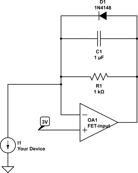
You can also use an IV converter:

schematic

simulate this circuit – Schematic created using CircuitLab

The opamp replaces the LDO and will make sure your device is powered by a constant 3V, while giving a current reading on the 1k resistor. The cap keeps the opamp stable. The diode should be enough diodes in series to allow the opamp to supply the device directly, bypassing the resistor, if needed. It is optional.

If your device has onboard caps, you'll need to add a resistor in series because the opamp won't like the capacitive load.

\$\endgroup\$
1
  • \$\begingroup\$ If this works well with powering through a capacitor then maybe it would work. I don't need to measure current at any one point, I need to measure energy used over a certain time period. Maybe 1hr or less. So if I can use the capacitor to power and let me know how much energy was used then it would be good. \$\endgroup\$
    – Fraggle
    Commented Aug 27, 2017 at 22:03
1
\$\begingroup\$

What you want to do is integrating the current consumption over time to get the average value.
Your device might most likely be in advertising (or connected) mode only.
The biggest issue is the dynamic behavior of the current profile: While most of the time the bluetooth chip will be in low-power mode (no Tx/Rx) its current consumption will be in the range of (very few) micro-amps, but (every now and then) it will wakeup for just a few milli-seconds for processing the ADV/CON packets that have peak consumption up to tens of milli-amps.
The amount of charge (or average current) from the low-power mode might be in the same range (or even higher) than that of the pulsed packets.
So, a single measurement with a single measurement range will give totally wrong results: if the measurement range covers the peak pulse current, there'll be so much noise and offset error in the low-power phases; but if the measurement range is good for the low-power phases the pulse currents will be clipped (ignored).
SMUs might sound great for such a job, as they can record current profiles; but they won't switch the measurement range fast enough.
If you have something to recorded two analog channels with sufficient speed and memory (>=100, better 1000 kSps, for the timeframe required - e.g. oscilloscope with deep memory), I'd propose to use two current shunts (with instrumentation amplifier, e.g. AD8422) in series, one for the small currents (e.g. 20µA range - with a bypass diode in parallel to limit voltage drop) and one for the packet pulses (e.g. 20mA range), capture the two current signals, and calculate together, based on a simple rule (use the low range when not out-of-range , otherwise use the high-range).
The idea with the capacitor discharge is also not bad, but you must consider its internal leakage - and (esp. for ceramic caps) there's voltage-bias effect reducing capacitance, so do not judge from delta-voltage, but from the required recharging back to the initial capacitor voltage level.

\$\endgroup\$

Your Answer

By clicking “Post Your Answer”, you agree to our terms of service and acknowledge you have read our privacy policy.

Not the answer you're looking for? Browse other questions tagged or ask your own question.