2
\$\begingroup\$

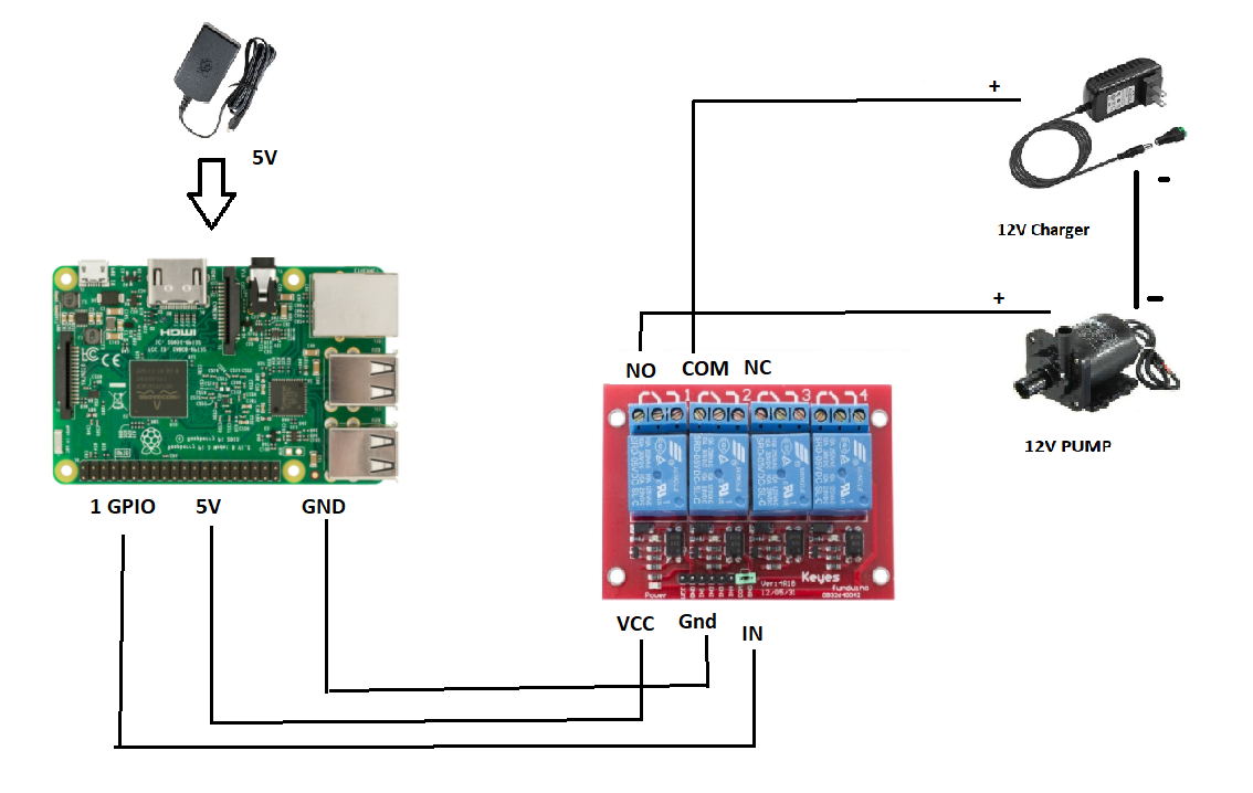
I'm building a small project where I will control a 12V water pump with my raspberry Pi.

I have made a small sketch of what I imagine should be a correct setup, but have been reading about the need for a flyback diode.

I'm new to electricity, so I'm not sure how to connect this. I just bought a pack of 1N4007 diodes. How should I connect it so that it protects my Raspberry Pi/relay from any arcs?

enter image description here

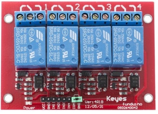
I have the following relay: enter image description here

Should I remove the jumper between COM/GND to separate the two power sources through the optocoupler?

Appreciate any help on this, thanks!

\$\endgroup\$
15
  • \$\begingroup\$ It'd be a good idea to post a link to the documentation for the relay board, but it looks to me like it has flyback diodes - it's probably the component on the bottom left of each relay. \$\endgroup\$
    – PeterJ
    Commented Aug 29, 2017 at 12:33
  • \$\begingroup\$ I think the relay board has a flyback diode incorporated. Do you have any data sheet for the relay board? \$\endgroup\$
    – TheOne
    Commented Aug 29, 2017 at 12:34
  • \$\begingroup\$ It would be a good idea to decide if you are going to switch the mains to the mains adaptor ("charger") or the low voltage to the pump. And is that mains adapter also being used to power the Raspberry Pi? \$\endgroup\$ Commented Aug 29, 2017 at 12:37
  • \$\begingroup\$ @PeterJ diode indicated is likely for the relay coil, not the load. An additional diode for the pump and possibly also a snubber circuit would be advisable. \$\endgroup\$
    – Trevor_G
    Commented Aug 29, 2017 at 12:53
  • 2
    \$\begingroup\$ Diode should be across the motor terminals, cathode to the PLUS side, anode to the negative side. \$\endgroup\$
    – Trevor_G
    Commented Aug 29, 2017 at 13:10

1 Answer 1

3
\$\begingroup\$

A diode needs to be placed across the motor as shown in the crude diagram below. The diode should be placed as near to the motor as reasonably possible. This will reduce the wear from arcing across the relay contacts, as you have read.

What you should also try to do is prevent the sudden current change when a relay is energised from affecting the Raspberry Pi - you don't want it to have any chance of experiencing a voltage drop ("brown out") that resets it.

You can do that by using separate wires to the 5 V PSU and placing a decoupling capacitor (maybe 33 µF or whatever you have to hand around that value, or you can go and find out how to calculate the minimum required value) across Vcc-GND as close to the pins for them on the relay board as reasonably possible. The capacitor acts as a little reservoir of energy right next to where it is needed. For best results when doing that, also separate the common ground of the optoisolators from the relay coil ground.

I tried to emphasize that the power to the relay board and the power to the RPi should be kept separate in this circuit diagram:
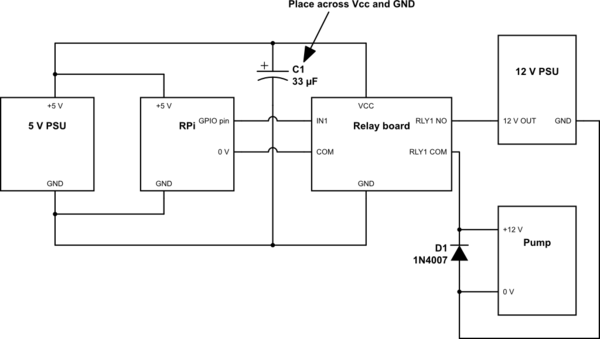
schematic

simulate this circuit – Schematic created using CircuitLab

A bit of heatshrink to put over any wire-to-wire solder connections that you make might be a good idea to keep things safe and tidy - it's less messy than electrical tape.

\$\endgroup\$

Your Answer

By clicking “Post Your Answer”, you agree to our terms of service and acknowledge you have read our privacy policy.

Not the answer you're looking for? Browse other questions tagged or ask your own question.