0
\$\begingroup\$

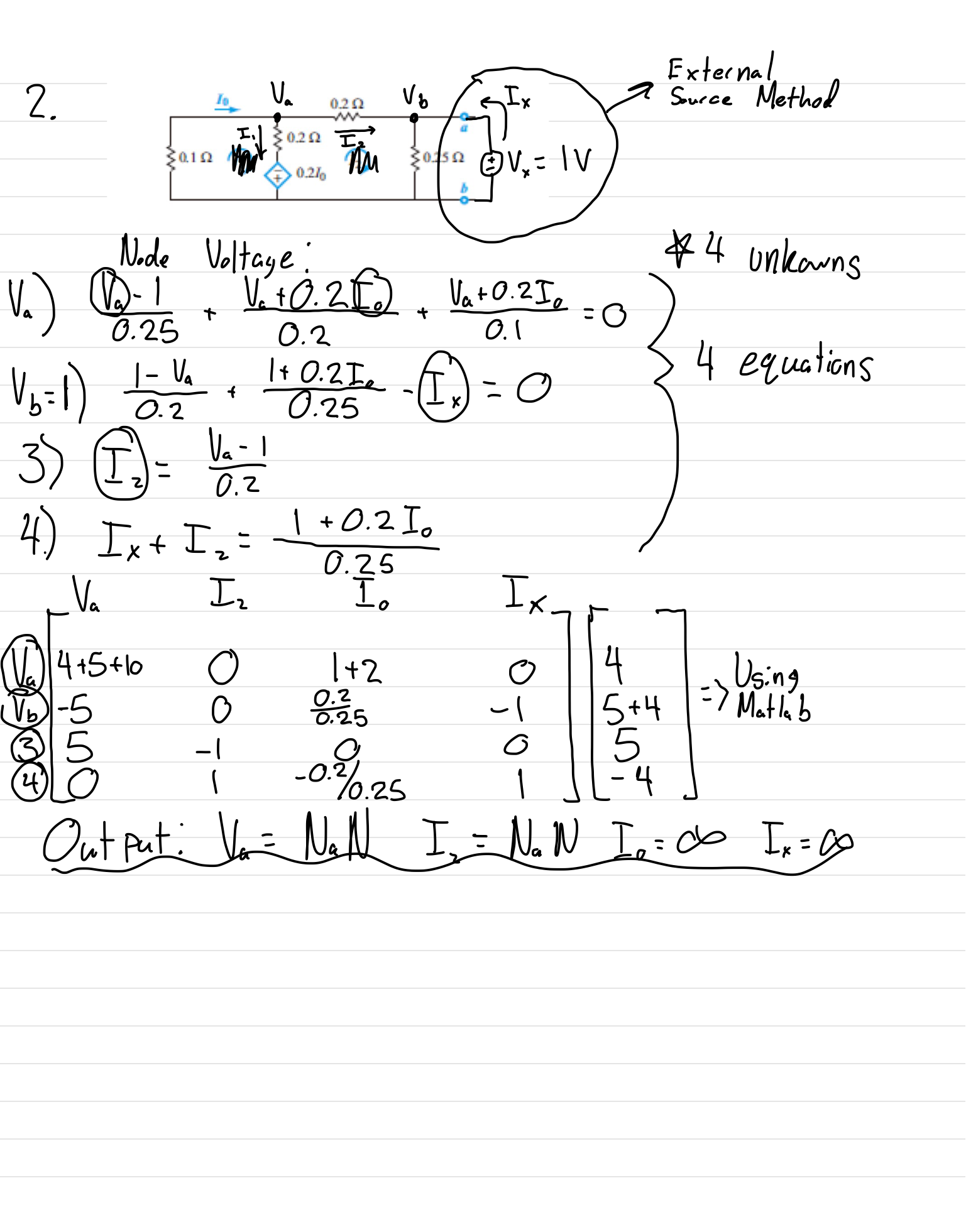
I am given this question The given question as is

I have 2 questions:

1) Is my work wrong? I am assuming so since I am getting some funky answers. If I am wrong, will you please point out what I should have done differently?

2) Since he didn't add a ground I figured I would have to consider the entire bottom wire as + 0.2I_0 because of the dependent source, but would I also have to consider my external voltage (V_x) in some way? If so, how would I add it into my work?

Problems I had with this question:

1) There is no ground, I am not familiar with problems like this.

2) I was not sure what equations I needed for all my unknowns. The equation that feels most like it doesn't belong is Equation 2, but I could not find any better approach.

Thanks!

Here is my attempt to solve for R_th: Attempted Solution

\$\endgroup\$
3
  • \$\begingroup\$ Your first equation has a term \$V_a / 0.25\$ but there's no 0.25 ohm resistor connected to node A, so this is likely an error. \$\endgroup\$
    – The Photon
    Commented Sep 7, 2017 at 21:01
  • \$\begingroup\$ Maybe you got confused because the original problem labelled two nodes as 'a' and 'b', but then you defined a different node as 'a' and the one that was originally 'a' you re-labelled as 'b'. Keep your node labels straight and it will be much easier to come up with consistent equations. \$\endgroup\$
    – The Photon
    Commented Sep 7, 2017 at 21:03
  • \$\begingroup\$ I definitely goofed that up. I will fix that ASAP and post a new but I still get NaN values in Matlab \$\endgroup\$
    – Smeboo
    Commented Sep 7, 2017 at 22:29

1 Answer 1

0
\$\begingroup\$

First of all, you can have "ground" wherever you want. In this case, "ground" is just a theoretical reference point for all of your voltages, a point at which you say the voltage (or potential difference) is 0 and all other voltages are compared to. The best place would certainly be node b.

The fact that you have a voltage source positioned "upside down" has no effect on this, it just means that the voltage on the other side of the source will be negative.

Next, you should look into superposition. It makes things pretty easy to solve. I would start with the known voltage first:

  • Treat the dependent voltage as a short
  • Find out the voltages at all the different points

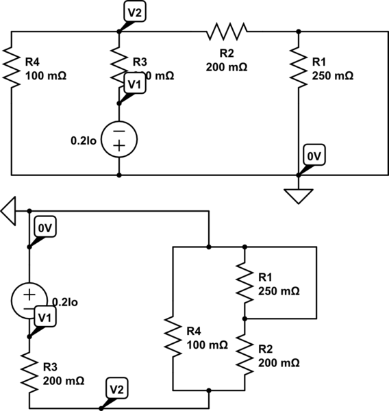
schematic

simulate this circuit – Schematic created using CircuitLab

  • Lump all the resistances together, giving a single 4/31 ohm resistor
  • Get the current through this due to your source, which is 7.75A

    -Now find the voltages due to the dependent voltage

schematic

simulate this circuit

  • The second diagram is just a rearrangement of the first, making it obvious that R4 and R3 form a potential divider. This means v2 is -1/4*0.2Io, and v1 is -0.2Io.

  • Now we can sum the superpositions, giving a V2 of ((-Io/20) + 0.25Vin)

  • The current through R4 is equal to Io, so it would be useful to get this. We know the voltage on both sides, so we just do Io=(0-((-Io/20) + 0.25Vin))/0.1
  • After a bit of maths, we get Io=-5Vin
  • This means that V1=Vin
\$\endgroup\$
9
  • \$\begingroup\$ Superposition doesn't apply here since there's only one independent source (the test source to be applied to the port). \$\endgroup\$
    – The Photon
    Commented Sep 7, 2017 at 20:57
  • \$\begingroup\$ I'm pretty sure you can still apply superposition even with dependent sources, as long as you stick with variables instead of absolute voltages until you sum all the superpositions \$\endgroup\$
    – BeB00
    Commented Sep 7, 2017 at 21:07
  • \$\begingroup\$ Say you zero out all the sources except the dependent source. Now whatever is the input controlling the dependent source will be a 0 (voltage or current). So the dependent source output will be 0. Not very useful, nor will it give you a correct result. More detail here \$\endgroup\$
    – The Photon
    Commented Sep 7, 2017 at 21:10
  • \$\begingroup\$ I'm not quite sure what you mean. Yes, if you connect 0V across the terminals, the dependent source will be 0V. When I simulate this circuit, V1 does seem to be equal to Vin. That link doesn't really explain why you shouldn't use superposition for dependent sources \$\endgroup\$
    – BeB00
    Commented Sep 7, 2017 at 21:12
  • \$\begingroup\$ electronics.stackexchange.com/questions/107435/… \$\endgroup\$
    – BeB00
    Commented Sep 7, 2017 at 21:41

Your Answer

By clicking “Post Your Answer”, you agree to our terms of service and acknowledge you have read our privacy policy.

Not the answer you're looking for? Browse other questions tagged or ask your own question.