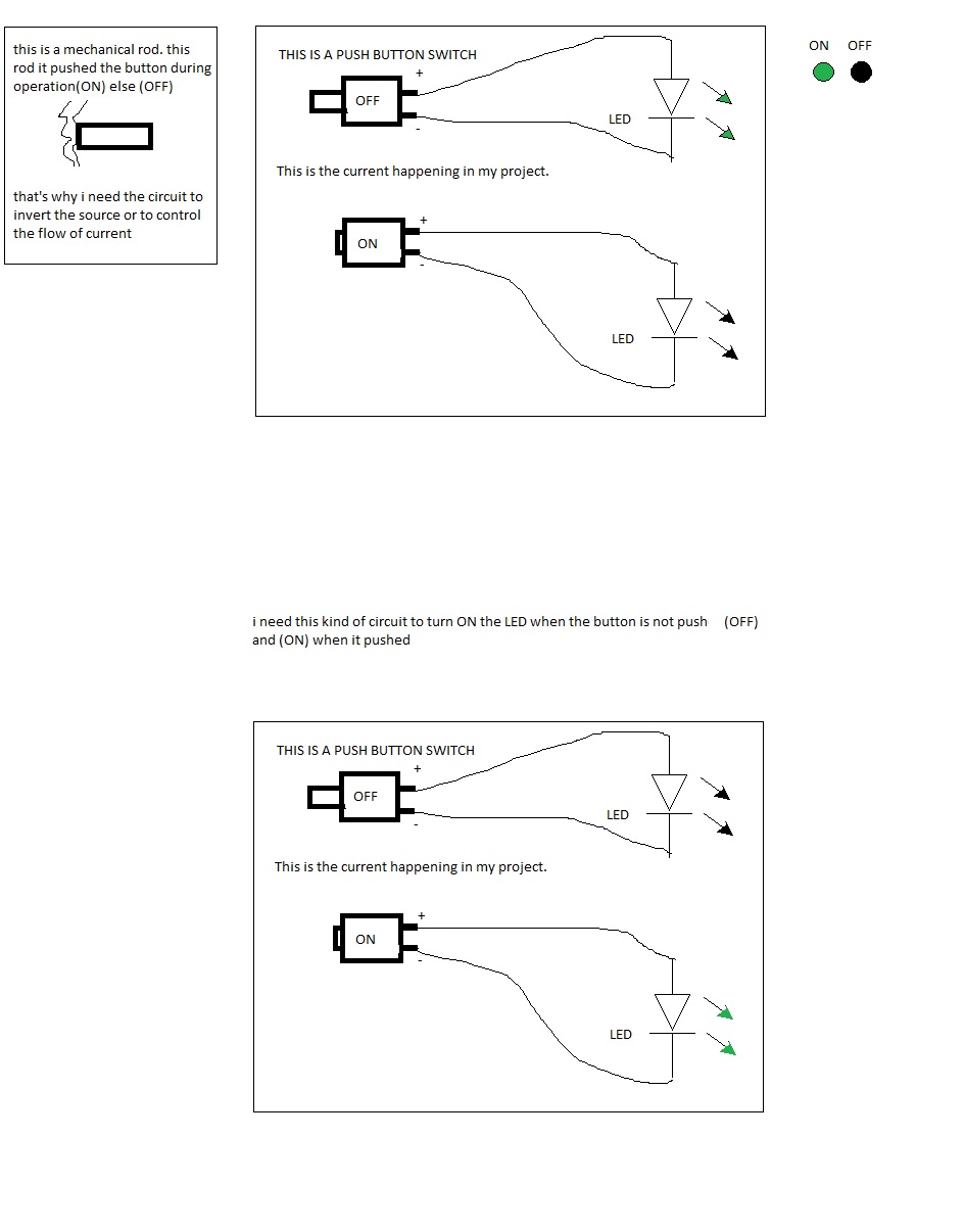
 how to create a circuit to TURN OFF LED WHEN SWITCH IS "ON" AND TURN OFF LED WHEN SWITCH IF "OFF" for 12v input?

simulate this circuit – Schematic created using CircuitLab
Figure 2. Basic schematic for original poster to edit.
 how to create a circuit to TURN OFF LED WHEN SWITCH IS "ON" AND TURN OFF LED WHEN SWITCH IF "OFF" for 12v input?

simulate this circuit – Schematic created using CircuitLab
Figure 2. Basic schematic for original poster to edit.
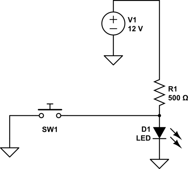
I think an easier way would be to use a pull-up resistor:

simulate this circuit – Schematic created using CircuitLab
When the switch is "off" (open, like displayed in the schematic), the voltage source provides current to the led through the resistor, so it turns it on. Assuming the LED's forward voltage is 2V, forward current is 20mA, the calculation for the resistor is as following:
V1 = I*R1 + Vf
R1 = (V1 - Vf)/I = (12-2)/20m = 500Ohm
When the switch is "on" (closed), the current provided by the voltage source V1 flows to ground, so the LED does not turn on. Or you can think of it as the anode of the LED having 0V, like it's cathode, therefore not turning on.
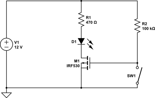
You have added the tag "mosfet" so I assume you want to turn the LED on and off with a FET. I am also guessing that you want the LED to turn ON when the switch is OFF. Here's one way to do it:-

simulate this circuit – Schematic created using CircuitLab
When SW1 is off, MOSFET M1 receives +12V on its Gate via R2. This causes the FET to turn on and light the LED. When SW1 is on it applies 0V to the Gate so the FET turns off.
When the switch is on a small current of 12V/100k = 120uA flows through R2. If this is too much then you can increase its resistance. However the higher the resistance the more sensitive the circuit will be to electrical or electromagnetic interference and leakage currents when the switch is off.