12
\$\begingroup\$

From time to time I hear (and read) that it is not good to make separate Gnd planes for digital and analog circuit parts. It's all summarized in this rule of thumb: "Don't split the Gnd plane, don't make gaps in it." Usually this comes without clear explanation.

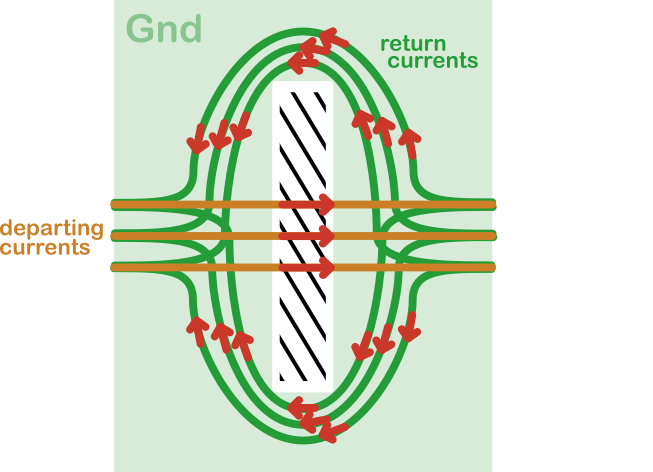
The closest I got to an explanation is this link: http://www.hottconsultants.com/techtips/tips-slots.html . The author points out that return currents will bend around the gap, such that the surface areas of the currents get large (borders of that surface area are defined by 'departing' and 'returning' current):

enter image description here

The return currents of the different signals are squeezed together at the corners of the gap, leading to cross-talk. The larger surface area of the current loops will emit and pick up EMC.

So far, so good. I do understand that no signals should be routed over such gap. Presuming you keep that rule in mind, would it still be bad to make gaps in the Gnd plane (eg. making a split between analog and digital circuit parts)?

\$\endgroup\$
6
  • \$\begingroup\$ This is a quite often debated topic, with certain people disagreeing vastly on what you should and shouldn't do (keep grounds separate, or don't keep them separate, etc.). Keep in mind this also depends on what you want to do. For example, with a stable voltage reference you tend to want some form of star-grounding, such that no return currents from other sources can come along and shift your values. A few uV can be enough when you are dealing with 10's of ppm at a few volts precision. \$\endgroup\$
    – Joren Vaes
    Commented Sep 16, 2017 at 8:03
  • \$\begingroup\$ Thank you very much @JorenVaes . When you mention "some form of star grounding", how do you practically accomplish that? I mean, how can you make a star ground with solid ground planes? \$\endgroup\$
    – K.Mulier
    Commented Sep 16, 2017 at 8:24
  • \$\begingroup\$ By not using a solid ground plane, I think. I am not an expert in this, and I usually limit myself to analog PCB's that don't use solid ground planes. \$\endgroup\$
    – Joren Vaes
    Commented Sep 16, 2017 at 8:34
  • 2
    \$\begingroup\$ Do you realize you've drawn a planar slot antenna? Antennas both radiate, which you may not want, and receive interference, which you may not want. Another link. \$\endgroup\$ Commented Sep 17, 2017 at 0:28
  • \$\begingroup\$ Very interested remark @EricTowers , I didn't realize that actually :-) \$\endgroup\$
    – K.Mulier
    Commented Sep 17, 2017 at 11:51

4 Answers 4

11
\$\begingroup\$

High frequency return currents want to follow the outward currents due to inductance.

If you force the return currents to take a different path then a couple of bad things happen.

  1. You create a loop that can receive and transmit magnetic interference.
  2. You introduce extra inductance in the signal path which can reduce signal integrity.

Note that digital signals with fast edges can produce strong high frequency spikes even if the switching rate is low.

Note also that the outward path may not always involve just tracks, it may be inside a component. Even if a component has separate analogue and digital power and ground pins there are likely to be some signals crossing over the boundary inside the chip.

OTOH at low frequencies currents take paths determined primerally by resistance. So splitting planes can be a useful technique to influence the path return currents take and avoid shared impedance.

If you have exactly one place where signals cross the mixed-signal boundry then splitting the plane makes a lot of sense, it forces analog return currents to stay on the analog side and digital return currents to stay on the digitial side.

If you have multiple places where signals need to cross the mixed signal boundry (i.e. multiple ADCs, multiple analog switch chips etc) then the benefits of splitting get much more questionable. Each mixed signal chip needs a connection between the two planes but once you put multiple connections between the planes you lose a lot of the benefits of splitting them in the first place.

\$\endgroup\$
1
  • 1
    \$\begingroup\$ Thank you very much. Suppose I have just one ADC crossing the gap. Where exactly should I connect the AGND and DGND planes? On this page (electronics.stackexchange.com/questions/306862/…) I read: 'Let's name your two grounds AGND and PGND (analog and power). Some say to split, and join AGND/PGND or AGND/DGND under the ADC. This means any current that runs between AGND and PGND has to flow in the ground link under the ADC now, which is the worst possible place.' But I'm not sure if that statement is correct. \$\endgroup\$
    – K.Mulier
    Commented Sep 16, 2017 at 11:46
7
\$\begingroup\$

The reasoning is very similar to the trend away from split grounds for digital & analogue. Its all about return current

There has actually been a trend away from split ground planes and instead concentrating on placement separation AND consideration for the return current path.

  • Do not split the ground plane, use one solid plane under both analog and digital sections of the board
  • Use large area ground planes for low impedance current return paths
  • Keep over 75% board area for the ground plane
  • Separate analog and digital power planes
  • Use solid ground planes next to power planes
  • Locate all analogue components and lines over the analogue power plane and all digital components and lines over the digital power plane
  • Do not route traces over the split in the power planes, unless if traces that must go over the power plane split must be on layers adjacent to the solid ground plane
  • Think about where and how the ground return currents are actually flowing
  • Partition your PCB with separate analog and digital sections
  • Place components properly

Mixed-signal design checklist

  • Partition your PCB with separate analog and digital sections.
  • Place components properly.
  • Straddle the partition with the A/D converters.
  • Do not split the ground plane. Use one solid plane under both analog and digital sections of the board.
  • Route digital signals only in the digital section of the board. This applies to all layers.
  • Route analog signals only in the analog section of the board. This applies to all layers.
  • Separate analog and digital power planes.
  • Do not route traces over the split in the power planes.
  • Traces that must go over the power plane split must be on layers adjacent to the solid ground plane.
  • Think about where and how the ground return currents are actually flowing.
  • Use routing discipline.

Remember the key to a successful PCB layout is partitioning and the use of routing discipline, not the isolation of ground planes. It is almost always better to have only a single reference plane (ground) for your system.

(pasted from the below links for archiving)

www.e2v.com/content/uploads/2014/09/Board-Layout.pdf

http://www.hottconsultants.com/pdf_files/june2001pcd_mixedsignal.pdf

\$\endgroup\$
6
  • \$\begingroup\$ Thank you very much. Very interesting answer. So your advice about the Gnd- and power planes is: Make one solid Gnd plane for the whole board, and two separate Power planes - one for the digital and one for the analog part. Right? \$\endgroup\$
    – K.Mulier
    Commented Sep 16, 2017 at 12:03
  • \$\begingroup\$ pretty much. The key is to think about return currents for everything when it comes to layout \$\endgroup\$
    – user16222
    Commented Sep 16, 2017 at 12:06
  • \$\begingroup\$ What about routing a trace for each and every return current? I'm trying to do that right now on my design - sort of a test ;-) \$\endgroup\$
    – K.Mulier
    Commented Sep 16, 2017 at 12:07
  • \$\begingroup\$ you impair the ground continuity. Sometimes this is needed (I am looking ad doing this for phase current measurement) but these are the exception not the norm. Remember the return current field strength \$\endgroup\$
    – user16222
    Commented Sep 16, 2017 at 12:11
  • \$\begingroup\$ What do you mean by "you impair the ground continuity" and "remember the return current field strenght"? \$\endgroup\$
    – K.Mulier
    Commented Sep 16, 2017 at 12:12
4
\$\begingroup\$

The #1 priority is placing stuff in the right place on your board.

For example, if you have the power entry connector on the left, the motor controller and its output connectors on the right, and the sensitive analog bits in the middle, you're off to a bad start.

Better place the power connector right next to the high current outputs, which makes high currents flow naturally in a manner that makes your job easier.

Also the best IMO is to use split planes (AGND, DGND), then place all components on the corresponding plane then, in the end... remove the split and turn it into a solid ground plane. This forces you to make a good placement.

For the rest, this question is more or less the same, I advise reading the answers.

\$\endgroup\$
9
  • \$\begingroup\$ Thank you very much. But why exactly would you remove the split in the end? \$\endgroup\$
    – K.Mulier
    Commented Sep 16, 2017 at 11:47
  • \$\begingroup\$ If you split, then all current that flows from one ground to the other will flow in the place they are connected, which is usually the ADC, ie, the worst possible place for this to happen! \$\endgroup\$
    – bobflux
    Commented Sep 16, 2017 at 11:55
  • \$\begingroup\$ Imagine the ADC chip like this: Analog part is a few an inputs, Digital part is the SPI bus. The return currents from the SPI bus flow back to the ADC chip. So they might cross from DGND into AGND, but even that should not happen if the layout is good. What other currents would cross from DGND into AGND? (I'm not criticizing your reply. I'm genuinly asking this question because I want to learn ;-) \$\endgroup\$
    – K.Mulier
    Commented Sep 16, 2017 at 12:00
  • \$\begingroup\$ Any common mode current that comes from the cables connected to your board, or ESD strike, capacitive coupling between the board and nearby metallic stuff, lots of possibilities... \$\endgroup\$
    – bobflux
    Commented Sep 16, 2017 at 12:17
  • 1
    \$\begingroup\$ As for power planes like AVCC and DVCC, don't connect them, you'd put a filter between them like ferrite bead, or even use separate regulators, lots of options. DVCC will be noisy, and the noise should not spread to analog supplies. \$\endgroup\$
    – bobflux
    Commented Sep 16, 2017 at 12:29
1
\$\begingroup\$

This is a difficult topic often with contradictory information. One common example where this comes up is when laying out the copper for analog to digital converters. Often the datasheets specify keeping the analog ground return separate from the digital portion and only tying them together at one point. The datasheets often specify that specified accuracy can only be achieved when the chip is grounded in this way.

If the entire board was one AtoD chip then this would be easy but when you start mixing DtoA's, Op amps, comparators, and digital circuits, this quickly becomes impractical.

I won't rehash what others have said about good layout practices. Similar to resistors in parallel, current will flow in the path of least resistance. At high frequency, the inductance of boards can contribute significant reactance. The path of least reactance for the return current would be right underneath the signal trace in the ground plane.

When there are gaps in the ground plane, the return current has to take a longer path back to the source which results in a larger loop and higher inductance.

For more detailed information on this subject, I would recommend Electromagnetic Compatibility Engineering by Henry W. Ott. It is the bible on EMC.

\$\endgroup\$
0

Your Answer

By clicking “Post Your Answer”, you agree to our terms of service and acknowledge you have read our privacy policy.

Not the answer you're looking for? Browse other questions tagged or ask your own question.