2
\$\begingroup\$

I am looking at sizing a motor for lifting a mass a set distance in a set time and have found multiple design notes that have allowed me to complete this task. For example https://www.maxonmotor.com/medias/sys_master/root/8815460712478/DC-EC-Key-Information-14-EN-42-50.pdf?attachment=true or http://www.machinedesign.com/motorsdrives/how-pick-motors-linear-motion

However, my main qualm lies in understanding the ability to dictate and obtain a trapezoidal profile. Taking the the second source as an example, for acceleration/deceleration the torque required is 0.3582 Nm and 0.3309 Nm for constant velocity.

1) I understand the concept of the torque constant, but how do you control the current supply to obtain these constant torques for acceleration and constant velocity? Could it be implemented by measuring the current to the motor, turning off the voltage supply when it hits this limit, and turn it back on when it falls below, until it reaches the target speed and then turning off this limiter?

\$\endgroup\$
3
  • \$\begingroup\$ Velocity feedback loop and acceleration feedback loop. \$\endgroup\$
    – Chu
    Commented Sep 17, 2017 at 19:51
  • \$\begingroup\$ It depends on all your particular performance criteria; efficent fastest, smoothest , by limiting acceleration but also rate of change in accel., and ability to add either current and position or encoder and or vel. feedback. Comparing current may be done by any of several methods. Heatloss might be small and a simple method could be used. Trapezoidal velocity , triangular, ramped sine. These details depend on gear friction plus inertial mass, gravity assist, etc. The simplest method is just a linear current limiter then a pulsed current limiter, then a stored inductor current limiter. \$\endgroup\$
    – D.A.S.
    Commented Sep 17, 2017 at 20:10
  • \$\begingroup\$ Also does it need a holding torque and is it bidirectional? \$\endgroup\$
    – D.A.S.
    Commented Sep 17, 2017 at 20:20

1 Answer 1

4
\$\begingroup\$

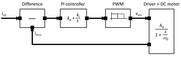
To control acceleration you need to measure one of two things: Current or Velocity.

Acceleration is the affect of torque being applied to some inertia & torque is proportional to current. Thus if you measure current & control current you will control acceleration.

Acceleration is the rate of change of velocity. Thus if you measure the velocity you can deduce acceleration.

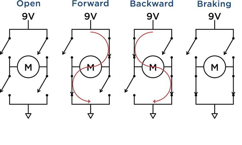
to implement this you will need a controller to generate an error term (be it current or velocity) & via a PI controller to generate a voltage demand to then generate the needed PWM to synthesis the needed voltage.

I would suggest controlling based upon velocity simply because controlling acceleration via Torque (ie current) is extremely dependant on the load profile. Equally if a DC motor is being used you can take credit for the velocity is proportional to the voltage applied & while this "constant" isn't really constant, it variation with stator current maybe low enough that you could operate open-loop with just a voltage profile.

enter image description here

enter image description here

\$\endgroup\$
2
  • 1
    \$\begingroup\$ Usually you have both. You have a closed-loop current control to be able to accurately maintain a certain torque and on top of this you have another closed-loop velocity control which outputs the setpoint for the underlying torque controller. \$\endgroup\$
    – Janka
    Commented Sep 17, 2017 at 21:25
  • \$\begingroup\$ I agree (all my controllers have both). It all comes down to complexity w.r.t. expected output. Sometimes you can "get away with" running an induction machine with a simple V/f controller... sometimes you need a full FOC . \$\endgroup\$
    – user16222
    Commented Sep 17, 2017 at 21:27

Your Answer

By clicking “Post Your Answer”, you agree to our terms of service and acknowledge you have read our privacy policy.

Not the answer you're looking for? Browse other questions tagged or ask your own question.