1
\$\begingroup\$

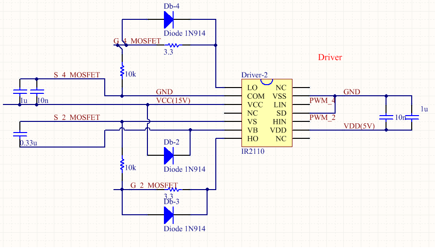
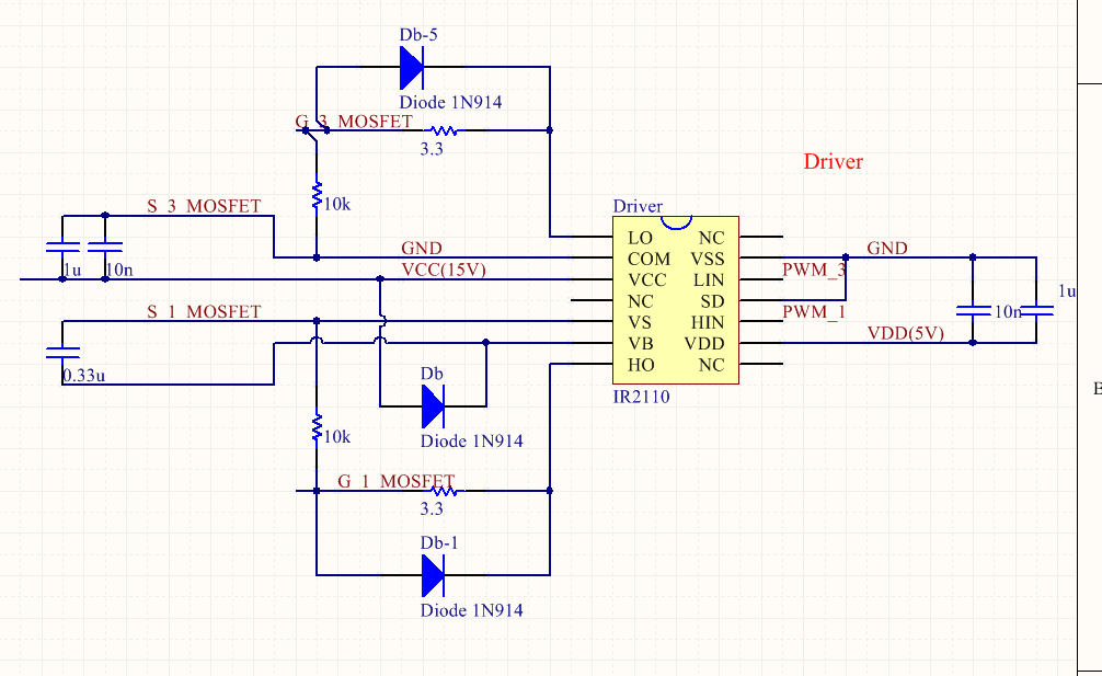
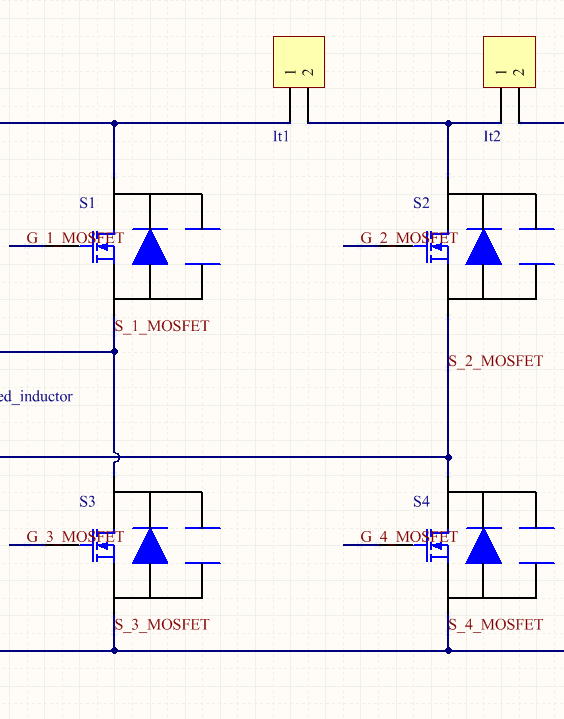
i'm new here and not English native. i'll be very appreciative of pointing out my grammar errors. i designed a new topology with four MOSFETs which low two operate as switches in 100kHz and high two are constant on.

however, the high side output is always low while the bootstrap capacitor is 15 volt. when i exchange the PWM signal, low side is constant on and high side is 100kHz switching signal, both low side and high side works. enter image description here
enter image description here

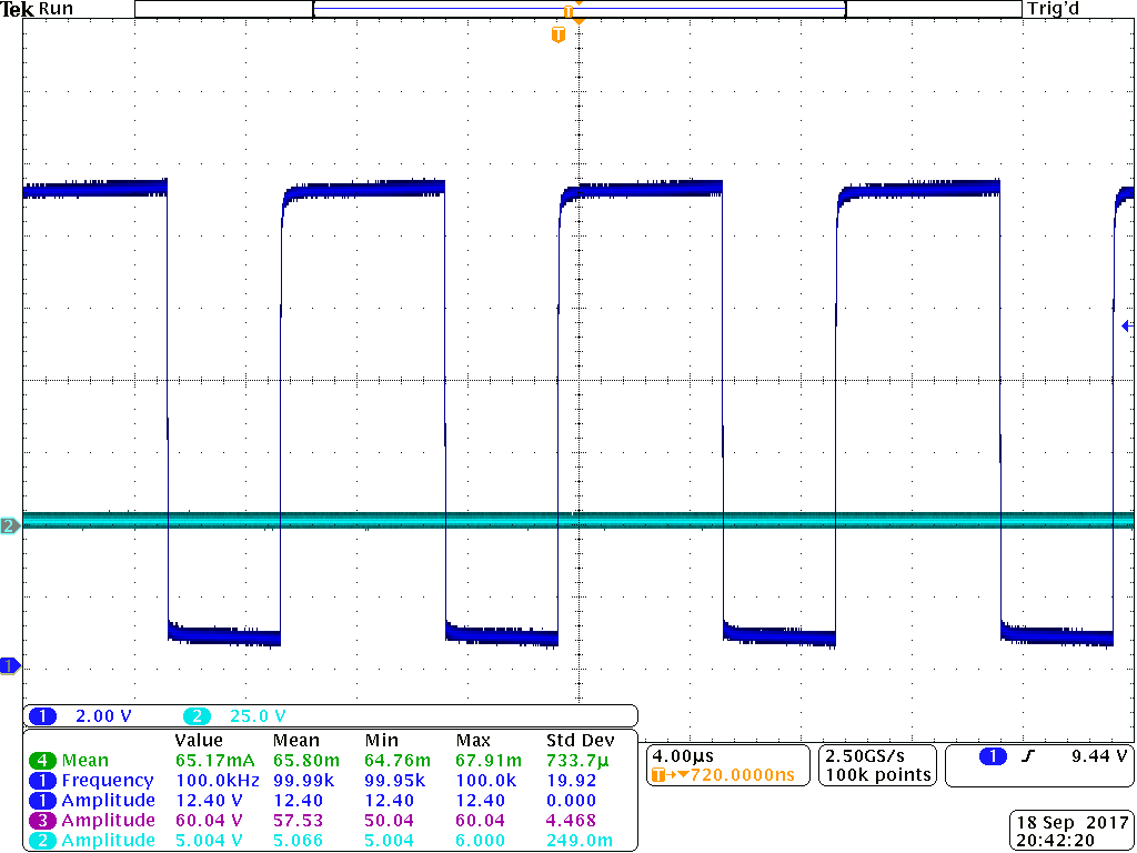
here are the layout and waveform. the dark blue is low side output and the light one is high side output. the MOSFETs are C3M0065090 enter image description here enter image description here
\$\endgroup\$
11
  • \$\begingroup\$ Good heavens! Right to left schematic direction! Show waveforms. What duty-cycle are you running? \$\endgroup\$
    – winny
    Commented Sep 18, 2017 at 12:58
  • \$\begingroup\$ duty cycle is 60% and 100kHz. the low side output is normal PWM with expected values, high side output is always zeros. \$\endgroup\$
    – Rust
    Commented Sep 18, 2017 at 13:11
  • 1
    \$\begingroup\$ Show oscillograms. Show layout. \$\endgroup\$
    – winny
    Commented Sep 18, 2017 at 13:14
  • 1
    \$\begingroup\$ What you need is a dedicated high-side supply rail, say from an auxiliary supply (like a small flyback converter) and a standard driver IC. This will allow you control over the gate plus allow you to keep it on as long as you wish. \$\endgroup\$ Commented Sep 18, 2017 at 13:57
  • 1
    \$\begingroup\$ Listen to Adam, you need a floating supply to give you ~15 V on top of your positive supply rail. \$\endgroup\$
    – winny
    Commented Sep 18, 2017 at 14:24

1 Answer 1

1
\$\begingroup\$

You cannot do always on for the high side unless you supply an external bootstrap voltage 12V or so greater then the high side source voltage, this should be obvious if you think about how the bootstrap cap and diode is supposed to work.

In fact most drivers will force the high side off if adequate voltage is not present across the boostrap cap to avoid accidentally running the high side in its linear region.

\$\endgroup\$
5
  • \$\begingroup\$ but the bootstrap capacitor voltage is 15V and i have done this in perf board with IR2110 \$\endgroup\$
    – Rust
    Commented Sep 18, 2017 at 13:39
  • 1
    \$\begingroup\$ Not 15V relative to ground, 15V relative to the high side mosfets source.... This is a charge pump and only works when the high side if off sufficiently often for the boost cap to recharge via the diode. You have 10k connected gate/source and a 0.33uF boost cap, so how long can the high side stay on before the charge on that cap becomes insufficient to hold the gate solidly above threshold? \$\endgroup\$
    – Dan Mills
    Commented Sep 18, 2017 at 14:02
  • \$\begingroup\$ @Rust Show waveform/oscillogram of that! \$\endgroup\$
    – winny
    Commented Sep 18, 2017 at 14:03
  • \$\begingroup\$ @winny i shown them in the answer below because i cannot put more than two pictures in the question, i'm sorry \$\endgroup\$
    – Rust
    Commented Sep 18, 2017 at 14:06
  • \$\begingroup\$ @DanMills the 0.33uF bootstrap capacitor's voltage is 15V . it's stable . \$\endgroup\$
    – Rust
    Commented Sep 19, 2017 at 6:17

Your Answer

By clicking “Post Your Answer”, you agree to our terms of service and acknowledge you have read our privacy policy.

Not the answer you're looking for? Browse other questions tagged or ask your own question.