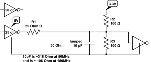
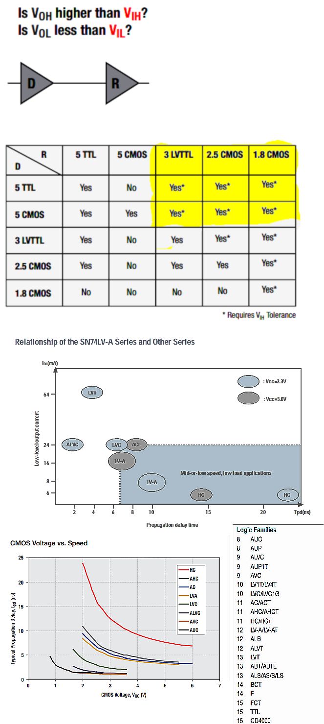
I'm trying to design a circuit to convert a 50 MHz clock source from 5 V to 3.3 V. At first, I thought of using Sparkfun's level translator shown in the link below:
https://learn.sparkfun.com/tutorials/bi-directional-logic-level-converter-hookup-guide
However, the NMOS used there, the BSS138, has delay and rise times that are unsuitable for the 50 MHz clock signal. It has a delay time of 2.5 ns and a rise time of 9 ns when turning on. Similarly, it has a 20 ns delay and a 7 ns fall time when turning off.
I tried to look for solutions that are similar to the converter, but most of them don't seem to be suited for MHz signals. Some solutions show using ICs such as the SN74LVC8T245, but it's direction depends on the input to the direction pin, and the rise times seem unsuitable given the clock signal. Other solutions such as a resistor divider seem to work for lower frequencies, but I want to ensure signal integrity as this is a clock signal. Using a faster NMOS would be ideal and simplistic, and I can replicate the Sparkfun circuit for multiple lines, but what other solutions would be optimal for this fast clock signal?
EDIT: Since there has been some discussion regarding the need for bi-directionalaity, I wanted to explain a bit here. Initially, we thought that we could go with the level translator. One channel would be available for shifting the clock from 5 to 3.3 V, and the remaining channels would be used as needed for other purposes. But, due to the specs of the BSS138, it didn't seem reliable for our 50 MHz clock. After some discussion, being bi-directional is no longer a requirement, at least for the clock signal, so we're just focusing on shifting the clock down for now. I'm really sorry about mentioning bi-direction. Let's just forget about it for now. We plan for the clock signal to be stepped down, and then it should go into another module that accepts 3.3 V as an input. I don't know the load capacitance or impedance of the module, but when I find that out, I'll update here accordingly.
EDIT: So, after ignoring the bi-directional functionality, I think I may have found a potential solution: to use a buffer to step it down from 5V to 3.3 V while keeping signal integrity. I found some buffers that seem to work from TI, the SN74LV1T34 and the SN74LV1T126.
http://www.ti.com/product/SN74LV1T34/description
http://www.ti.com/product/SN74LV1T126/description
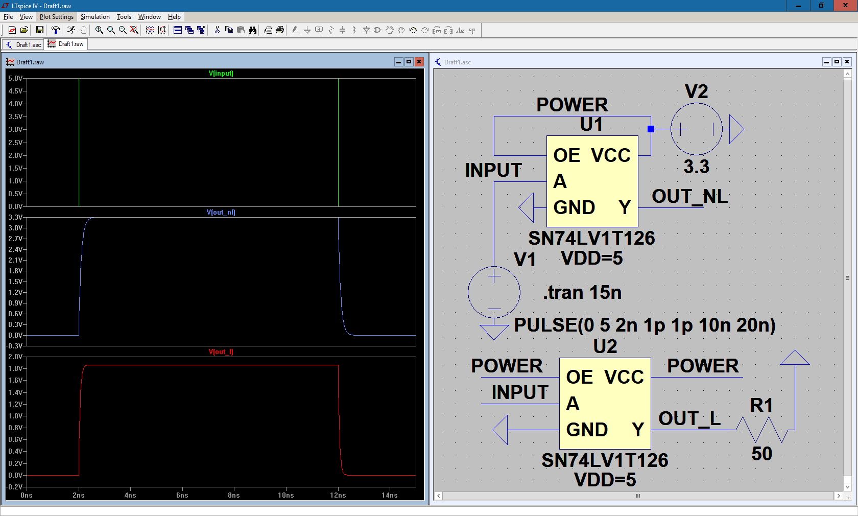
I imported the model of the SN74LV1T126 into LTspice and ran a simulation, hooking it up to 3.3 V and a 50 MHz 5-volt clock source, showing the output voltage with and without a load. Ideally, I would have liked to test out the SN74LV1T34, but there are no SPICE models available for it, so I'm just working with the SN74LV1T126. The image is shown below:
Here, I'm just showing one clock cycle so that I can measure the rise and fall times to see if it is within acceptable tolerances given the clock input. Judging by the sim, it seems to work well, but when under a load, it doesn't reach 3.3 V, but rather it falls down to 1.8 V. Since this is going to be hooked up to a module, it will be under load, so is there anything I can do to ensure it reaches the correct voltage?


