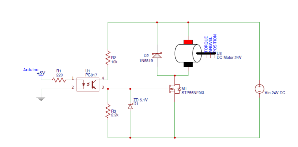
I have been working on it for two weeks in this project. Last day I have built a circuit to control the DC Motor speed that is shown in the image here. I have seen some questions like this in this forum and take those as references to build a circuit. But My circuit is not working at all. Here is the measurement I have given as input to the circuit and some voltage measurements.
I/P for optocoupler 5V from Arduino, VGS of MOSFET is 3.9V. VDS of MOSFET is 24V.
According to the datasheet, input voltages are enough for this circuit. But I don't know which causes the problem in this circuit. The motor is 24V DC and it is not running when connected with this circuit. What must be the problem here? Help, please!

Links for DATASHEET:
MOSFET STB55NF06L: http://www.st.com/content/ccc/resource/technical/document/datasheet/49/c5/a8/71/93/60/4f/86/CD00002690.pdf/files/CD00002690.pdf/jcr:content/translations/en.CD00002690.pdf
OptoCoupler PC817: http://www.sharp-world.com/products/device-china/lineup/data/pdf/datasheet/pc817xnnsz_e.pdf
Schottky Diode 1N5819 : https://www.vishay.com/docs/88525/1n5817.pdf
