0
\$\begingroup\$

I'm trying to analyze the below circuit. It's a textbook problem (Malvino's Electronic Principles) and the answer is given in the back (8966), but I am unable to reach that answer or approximation.

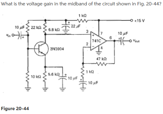
The goal is to figure out what is the total voltage amplification of the below circuit:

enter image description here

The Op-Amp part is pretty easy, since it's simply a non-inverting amplifier with a feedback configuration, so the amplification is (47k/1k + 1 = 48).

For the transistor, I'm having a difficult time. Particularly, the 1k resistor is throwing me off. I think it's in series with the voltage divider biased circuit, so I am approaching the analysis like this:

\$I_E = (15(10/33)-0.7)(1/5600) = 36.4 mV\$ (assuming 1k, 22k, 10k resistors form a voltage divider)

\$r'_e = 25 mV/I_E = 36.4 ohm \$

\$r_c = 6800\$ assuming the input impedance of the 741c is very high

\$A = r_c / r'_e = 186.8 \$

Total Amplification = 186.8 * 48 = 8967 which gets me pretty close to the textbook's answer.

I don't know if my analysis is correct though. I tried to simulate the circuit in LTSpice, but I got a larger voltage drop across the 1k resistor than my analysis would suggest so I just wanted to see if anyone would approach differently.

Thanks

\$\endgroup\$

2 Answers 2

2
\$\begingroup\$

It is not a voltage divider. For AC signals we assume the capacitors to be a short, both 10uF caps are large enough for this so assume they're shorts.

So the AC input signal is directly on the base, do the 2 base resistors then still matter? Nope

Same for the 5.6k emitter resistor, it is shorted by 10 uF. So for AC this is a common emitter circuit. Only the 6.8k collector resistor matters for the gain.

The other three resistors are only for setting the DC biasing point.

\$\endgroup\$
2
  • \$\begingroup\$ Thanks for your answer. When you say only the 6.8k resistor matters for the gain, I think you mean after the dc bias has been set, correct? And I think the 1k resistor impacts the dc biasing by acting as a voltage divider. Is that correct? \$\endgroup\$
    – Tyler
    Commented Sep 24, 2017 at 16:28
  • \$\begingroup\$ after the dc bias has been set, correct? To be able to determine the small signal gain you must first determine the DC bias point = dc bias. Does the 1k resistor influence the DC solution? I think it does. So yes, it has to be considered for the DC solution. Stop seeing voltage dividers everywhere. The voltage across the 1k resistor is determined by using Ohm's Law. But ignore it first, assume it is a short. Then determine how much current flows through that point. Then you know roughly how much voltage is dropped, then recalculate including that drop. Gain will not change much though, \$\endgroup\$ Commented Sep 24, 2017 at 17:50
0
\$\begingroup\$

Emitter dynamic-resistance (dV/dI) is just 1/transconductance, at least at lower frequencies. At 0.8mA, that is 30 ohms looking into the emitter.

30 ohms and 10uF are 300uS tau, or 3.3Krad/second / 6.28, or 500 Hz. Your midband Freq should be a few octaves above that, e.g. 2KHz, for accurate gain of the bipolar.
[ my original answer used 5,000Hz and 20KHz; the ultimate gain only increases 1dB]

Ignoring Vearly effects, bipolar gain is Rc * gm or Rc / reac, 6,800 / 30 = 220.

The opamp, at 2,000Hz, has only 1MHz/2,000Hz = 500x openloop gain. The opamp topology promises 47/1 = 47X but with loop-gain-margin of 500/47 = 10.6 that gain is not being controlled by the opamp; expect gain to 1dB shy of 47.

Note the computed bipolar gain, times opamp gain, 220 * 47, is 10,400x, only 1dB higher than the "answer".

\$\endgroup\$
1
  • \$\begingroup\$ Thanks for your answer. It's a little over my head at the moment, but I will try to understand it better! \$\endgroup\$
    – Tyler
    Commented Sep 24, 2017 at 16:31

Your Answer

By clicking “Post Your Answer”, you agree to our terms of service and acknowledge you have read our privacy policy.

Not the answer you're looking for? Browse other questions tagged or ask your own question.