0
\$\begingroup\$

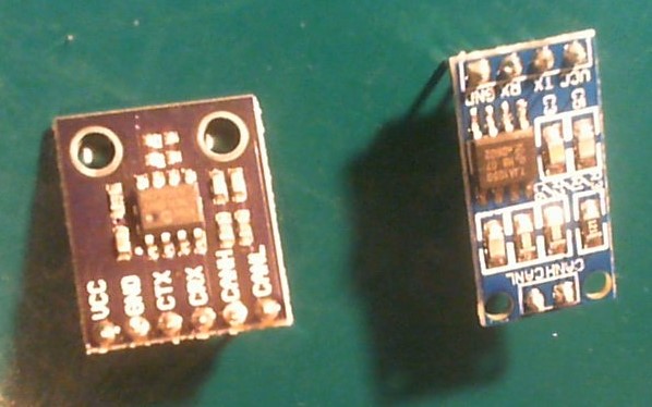
I bought different type of CAN transceivers: Two with an CJMCU2551 (left in the picture below). and four with TJA1050 (right in the picture below).

CJMCU2551 left, TJA1050 right

CJMCU2551 (left) has pins: VCC, GND, CTX, CRX, CANH, CANL, chip: MCP2551I (I think last is an I), written on back: CJMCU-2551

TJA1050 (right) has pins: VCC, GND, TX, RX, CANH, CANL (thus the same), chip: TJA 1050, written on back: LC Technology, www.lctech-inc.com

I have the feeling these are similar, although I see some difference, like the TJA1050 has an 120 ohm (terminator) resistor, but the MCU2551 has not.

Question 1: Are they interchangeable or not? (and if not, what should I take into account, like adding a 120 ohm resistor?)

I soldered pin headers to the pin holes, and I found out that all are not with 90 degrees angle. For the MCU2551 this was my own fault (I probably pressed to hard on the soldering iron so the angle is less than 90 degrees).

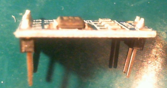
However, for the TJA1050 I could put both ends on a breadboard and the only way it fitted was like this: but when I took them out I saw the pins are in an angle.

Question 2: Why aren't the pins made in such a way both row ends (VCC, TX, RX, GND and CANL, CANH) fit in a breadboard with 90 degrees angle? (see pic below)

enter image description here

(I want to use them for STM32 (STM32F103C8T6 and STM32F407VET6) which all have CAN supported by GPIO pins).

\$\endgroup\$
8
  • 1
    \$\begingroup\$ The 120 ohm resistor is needed at two ends of your CAN network - depending on how many devices you have connected you may or may not want it at a certain node - as for the breadboard issue I suspect that it simply wasn't considered in the design, and not conforming to a breadboard-friendly pitch across the board may have reduced size (and thus cost) \$\endgroup\$ Commented Sep 24, 2017 at 22:37
  • \$\begingroup\$ @user2813274 I just want a one-to-one connection (so STM32 #1 -> CAN (#1) -> CAN (#2) -> STM #2 And for the breadboard problem it's ok I guess ... later when I built it on a PCB board it will look/work ok. \$\endgroup\$ Commented Sep 24, 2017 at 22:40
  • 1
    \$\begingroup\$ In the cast of a one-to-one connection you would ideally want a 120 ohm resistor at both ends, but if it's just short breadboard connections you can probably get away without it at an end - maybe you could have the pins hang off the breadboard or solder them in reverse and use some female jumpers or wire wrap for it to look cleaner \$\endgroup\$ Commented Sep 24, 2017 at 22:43
  • 1
    \$\begingroup\$ You can always add your own 120 ohm resistor between the two CAN wires near the termination point if needed - make sure you twist your wires once you do get to the 2 yard distance \$\endgroup\$ Commented Sep 24, 2017 at 23:24
  • 1
    \$\begingroup\$ At distance of 2 yards, or 6 feet, with wiring with dielectric constant of 4 to cause 6 feet to look like 12 feet, and then double (for round trip) to 24 feet, you have 24 nanoseconds delay versus 1,000uS fastest symbol rate. Almost any form of dampening will suffice with 24 nanosecond round trip. \$\endgroup\$ Commented Sep 25, 2017 at 3:57

0

Your Answer

By clicking “Post Your Answer”, you agree to our terms of service and acknowledge you have read our privacy policy.

Browse other questions tagged or ask your own question.