I've been looking at basic theory of Bipolar Junction Transistor.
In switching application design, in order to have a saturated transistor it is often required to find an appropriate value of the base current. By looking at the questions answered on the subject, people tend to use a ratio Ic/Ib much smaller than the parameter hFE,min found on the specific transistor datasheet. Some answer advise not to use a very low value of the raio Ic/Ib when dealing with fast switching applications, otherwise the transistor may not reach the fully on state in time.
After a quick look at wikipedia, there seems to be a lot of models for BJT. I was looking for some equations or charts relating the rise time and fall time of a transistor for a given Ic and Vbe; so far I found "nothing" (more like a lot of confusion in my head). This would be very helpful since I'd like to control the transistor with a PWM signal coming from a microcontroller (in my case a Raspberry, where the PWM signal is characterized by a frequency and dutycycle).
EDIT:
I've kept the question kind of general to get a basic understanding of the physique behind BJT, anyway as some of you pointed out, it would be helpful if I can provide more information.
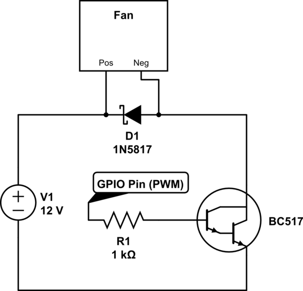
I want to drive a 12V 0.4A fan with Raspberry Pi 3 (application: thermal control). By connecting the fan directly to the 12V power supply I've measured the maximum current drawn, which is (not surprisingly) 0.4A. So I assumed Ic=0.4A. I only have three transistor types: TIP120, BC517, BC337. The latter is definitely not a good choice because of the low gain. I hated the idea of using one TIP120 to control only 0.4A so I decided to use BC517 (I'm not worryed about the heat dissipated: the fan is directly blowing air over the circuit).
Then I looked at what resistor I could use as base resistor. Long story short, I was lazy and nearby me there were only 1k resistors. Let see if I end up in saturation. Assuming Rb = 1k, from datasheet I found Vbe(on) = 1.4V, Raspberry GPIO pin output is Vpin = 3.3V, then: Ib = (Vpin - Vbe(on))/ Rb = 1.9 mA (which is well below the maximum output current of GPIO pins, so I'm good). The ratio Ic/Ib = 210; from datasheet \$h_{FE,min} = 30000\$. I would say the BC517 is saturated.
Now to the practical part: this is the circuit I'm using.

simulate this circuit – Schematic created using CircuitLab
With a ductycycle = 100%, I don't have to worry about the frequency of the PWM signal. I'm not sure If I remeber correctly, but I think I measured Vce = 0.85V. Given that, I was expecting to see a flowing current of (12V - Vce)/12V*0.4A = 0.37A. Instead, the maximum current drawn by the fan is 0.355A. There must be some other dissipative factors.
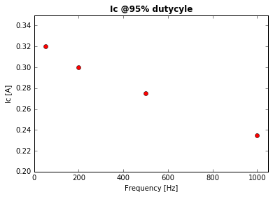
With dutycycle < 100% the frequency of PWM signal is definitely going to affect the switching performance. After setting the dutycycle = 95% and testing a few frequencies, this is what I've got (I only tested 4 frequency, then my multimeter battery dropped below the safe level so I stopped taking measures):
As you can see, the collector current decreases a lot by increasing the frequency. My guess: by increasing the frequency, the period of Ib get smaller and smaller. Eventually the rise time of the transistor may be longer than the dutycycle, hence there will not be a \$t_{on}\$ time.
This is what triggered my original question. It would be nice if there was a mathematical way to relate the transistor rise time, fall time, t-on time with Vbe and the frequency of the switching signal.

