1
\$\begingroup\$

Lets say an induction motor's spec sheet states the following:

1/ 50 Hz, 2-pole, full-load rotations-per-minute (RPM) = 2850.

2/ 60 Hz, 2-pole, full-load RPM = 3450.

Can we extrapolate this information to find out the full-load RPM for other frequencies (i.e.: 20 Hz, 30 Hz, 40 Hz, etc.)?


(SPECIFIC EXAMPLE)

Like for instance, as per here, the synchronous speed of the motor under 50 Hz is 3000 RPM. The full-load RPM then, is 95% (2850 / 3000) of the synchronous speed.

Doing the same thing for 60 Hz @ 3600 RPM, the full-load RPM is ~95.8% (3450/3600) of its synchronous speed.

Would it be reasonable to make an assumption that under different frequencies, the full-load RPM is ~95% of its corresponding synchronous speed?


EDIT From a suggestion by @Transistor, I am using a "VFD-B" variable frequency drive on my induction motor. (manual, website)

\$\endgroup\$
3
  • \$\begingroup\$ Note that both examples have the same slip frequency. This will depend on supply voltage and load but it makes some sense that it shouldn't be very dependent on frequency. So rather than a percentage, why not compute speed as synchronous speed - slip? \$\endgroup\$
    – user16324
    Commented Sep 27, 2017 at 19:02
  • \$\begingroup\$ Does that mean I should assume the same slip frequency for all other operating frequencies? I've got an induction motor hooked up to a VFD and just wanted to be sure of what the full-load limits are for any given frequency (from about 10 Hz to 60 Hz). \$\endgroup\$
    – plu
    Commented Sep 27, 2017 at 19:14
  • \$\begingroup\$ It's more likely to be correct than a fixed percentage. If you have the setup you can measure at some fixed (not necessarily full) load. \$\endgroup\$
    – user16324
    Commented Sep 27, 2017 at 19:29

3 Answers 3

1
\$\begingroup\$

enter image description hereYou can, but it makes little sense.

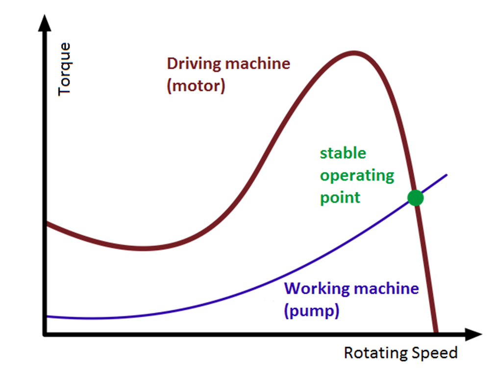
An induction motor behaves the same as a transformer, if you reduce the frequency, you had to reduce the voltage applied, too, otherwise the core —both the outer shell and the rotor— get overexcited and heats up.

If you reduce the voltage, the torque/speed characteristic shrinks proportionally in the torque direction. The actual full-load speed depends on the working point made from crossing the load characteristic with the motor characteristic.

So if an induction motor is built for 240V 50/60Hz, in reality it's a 240V 50Hz motor which would also work at 60Hz.

\$\endgroup\$
5
  • \$\begingroup\$ May I ask what you meant by "crossing the load characteristic with the motor characteristic"? \$\endgroup\$
    – plu
    Commented Mar 26, 2018 at 22:25
  • \$\begingroup\$ Please see the picture I added. \$\endgroup\$
    – Janka
    Commented Mar 26, 2018 at 22:28
  • \$\begingroup\$ Thanks for the clarification, from the origin of the picture, I'll look more into the concept of "Operating points" (en.wikipedia.org/wiki/Operating_point). \$\endgroup\$
    – plu
    Commented Mar 26, 2018 at 23:40
  • \$\begingroup\$ Uh, that's a really crude translation of the German article I wrote years ago. \$\endgroup\$
    – Janka
    Commented Mar 30, 2018 at 20:43
  • \$\begingroup\$ nptel.ac.in/courses/108106072/7 This is just FYI for anyone else, but a less crude explanation of "operating points" is in that web-course link, showing how that torque vs. speed curve for the induction motor is based on how its modeled, the fact that if the modeled torque is higher than the torque required by the load, the speed will increase until a stable operating point is reached. \$\endgroup\$
    – plu
    Commented Jul 11, 2018 at 22:32
2
\$\begingroup\$

It may be irrelevant. Many VFDs use slip compensation.

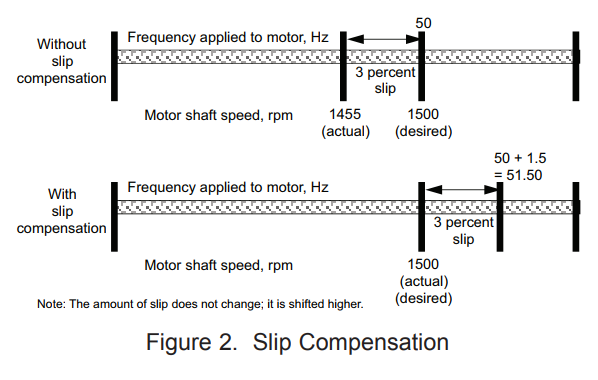
Slip Compensation Slip compensation is actually a sophisticated version of the open loop concept. The slip compensation method of speed control does not monitor the actual shaft RPM. Rather, it utilizes drive output current transducers to monitor the current drawn by the connected motor. As discussed earlier, when a load is placed on a NEMA B design motor during a situation where the output frequency is held constant, the slip increases, the shaft RPM slows and the motor current increases. The difference here is that the “slip” function “compensates” for the reduction in shaft RPM by increasing the voltage and frequency applied to the motor. Figure 2 illustrates an application that requires the motor to supply full torque at 1500 RPM.

enter image description here

The top portion shows what occurs without slip compensation. The applied frequency is 50Hz, but the motor actual shaft RPM, due to slip, has a value of 1455. The bottom portion shows how slip compensation automatically "compensates" this situation by applying 1.5Hz additional output frequency to the existing output frequency of 50Hz, resulting in a new output frequency of 51.5Hz. The motor shaft still "slips" back, but now the actual shaft speed is the desired 1500 RPM. The amount of slip does not actually decrease. It is simply shifted so that the actual RPM now is the desired RPM. Remember that the drive monitors current drawn by the motor, not the actual shaft RPM.

Read more at Yaskawa.

\$\endgroup\$
2
  • \$\begingroup\$ Thanks that's new info. to me; I don't think my VFD has this slip compensation though. Through tests, I can still clearly monitor reductions in shaft speed due to increased load (approaching the rated load). \$\endgroup\$
    – plu
    Commented Sep 27, 2017 at 20:21
  • \$\begingroup\$ Pop the link to the VFD user manual into your question and add the VFD tag. I'd say Charles Cowie will show up shortly thereafter. \$\endgroup\$
    – Transistor
    Commented Sep 27, 2017 at 20:39
1
\$\begingroup\$

At any operating frequency below the rated frequency, the full-load RPM of an induction motor controlled by a VFD should be quite close to the synchronous RPM minus the rated slip RPM. The rated slip RPM is the synchronous RPM at the rated frequency minus the full-load RPM at the rated frequency.

The VFD is designed to provide the voltage at any operating frequency that will result in that torque vs. slip operation. Sensorless vector drives adjust the applied voltage through the use of a mathematical model of the motor. At least thirty years ago very similar performance could be required by starting with a constant V/Hz profile, providing a manual adjustment to boost the V/Hz slightly at the low end of the frequency range, and providing an automatic "IR compensation" boost in proportion to torque estimated from output frequency and power. With senseless vector control, the adjustments are set automatically using a one-time "tuning" routine during commissioning. The results are more consistent and provide the desired results essentially down to zero speed and somewhat above 150% of rated torque.

The safe operating time at any given torque and speed below the rated speed depends on the motor design and cooling method. Many self-cooled motors designed for VFD duty can operate continuously at rated torque down to 1/3 of rated speed.

\$\endgroup\$

Your Answer

By clicking “Post Your Answer”, you agree to our terms of service and acknowledge you have read our privacy policy.

Not the answer you're looking for? Browse other questions tagged or ask your own question.