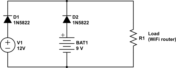
If it is time to be useful for a doubt not addressed here, let me know, meanwhile I will try to answer your two questions Q1 and Q2 as it goes.
Recommended solution for Voltage Dropout:
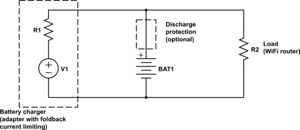
I understand you would prefer to focus on the relay solution, that I will discuss ahead, but a short word about the solution to mitigate the short voltage interruption - Using Diodes (regular ones as 1N4004 or Schottky as 1N5822) is the fastest commutation you can have. @Todor answered this very well here, so please see his post.
Relay-based solution:
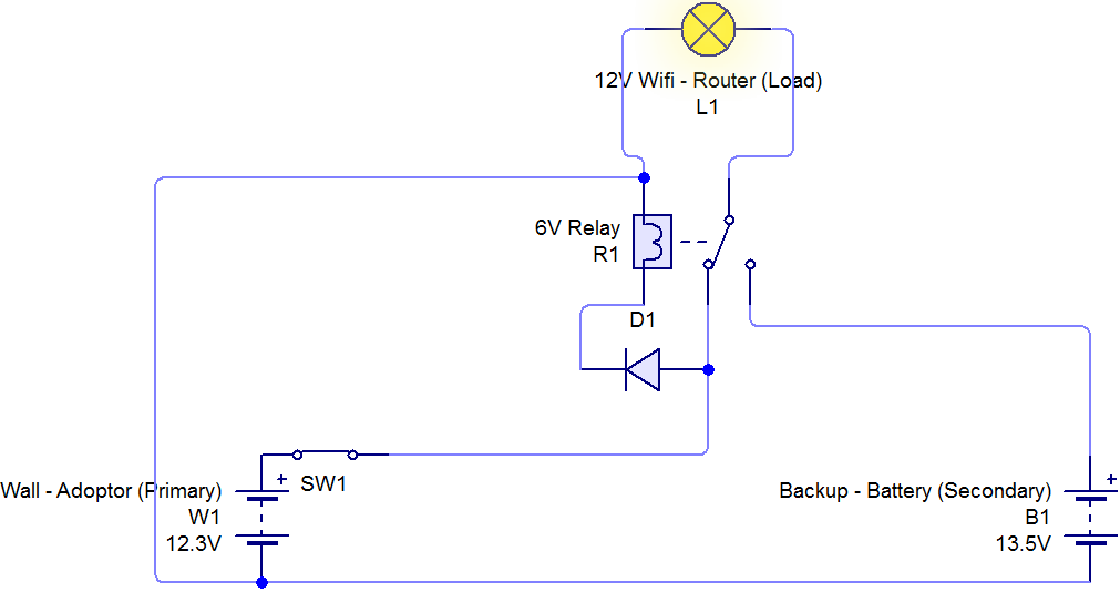
When PowerSupply (PS) loses power, it takes some time (possibly 0,1 ~ 0.5s) to decay the voltage. Most relays, and yours being 6V rated without further details, will just switch off when voltage drops to about 50% of relay's rated voltage = just 3V in your case. Contact switching time adds 10 ~ 20 ms.
The problem here is that the power source had to drop too much, going down to 3V, then wait that extra time, to become battery energized. So your load/router will receive power from the 13.5V battery too late and the router indeed will restart.
Q1. How do I step down from 12V to 6V, to power the relay?
Q1 & Improving the Relay-based solution:
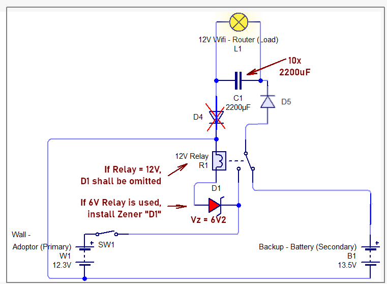
To reduce Heat and preserve service-life in the 6V relay, you could use a Zener Diode to drop the operating voltage. Assuming your relay has not a heavy-duty coil and would consume less than 140 mA @ 6V, then a 6.2V Zener diode as 1N4735A (1W, I.z <= 140mA) could create the voltage drop to make the relay see the 12VDC reduced to 6VDC.
Relay De-energization time: Curiously a 6V Relay with the zener diode will be more than 3x faster now, and probably faster than a 12V relay used at its rated voltage. Now the 6V relay just needs to drop from 12V to 9V, as due to a power outage, would make the relay coil reach 3V at coil much faster, to open the contacts. For a 12V relay, similar decay would need to go as low as 6V.
Q2. What kind of capacitor be use for the short term power in delay time?
Q2 & Capacitor sizing:
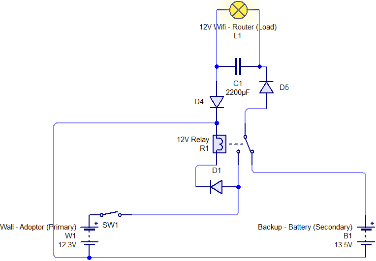
Without further information, I will assume your load/router consumes 1A in 12 V. This gives a load resistance equivalent to R = 12 Ohm. I would consider your marked 2200 uF as an initial guess. Calculation tools as here can show that the time constant is Tau = RC = 26ms. This is not adequate even to compensate for the switching time of the relay. Adopting then 10 units of 2200 uF, we will have Tau = 264ms. See the following picture, where I edited the generated graph:
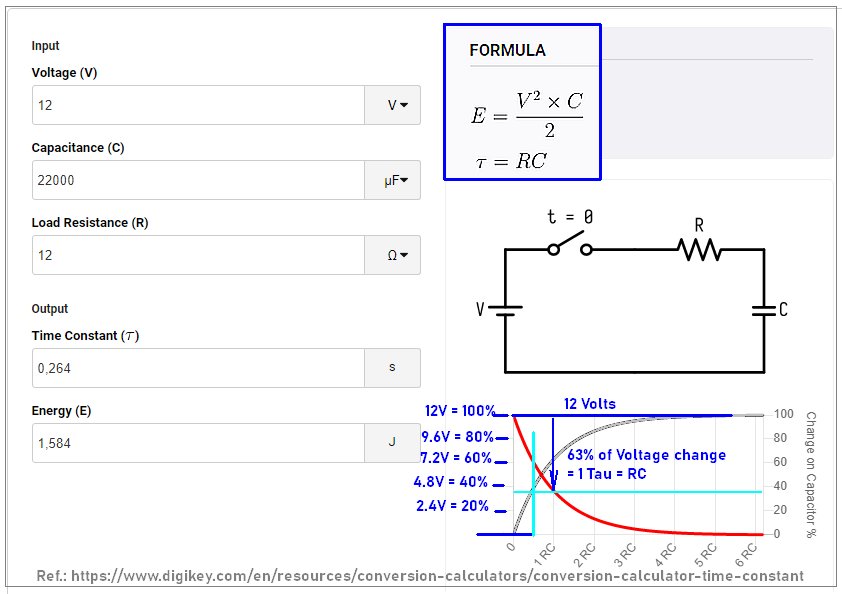
As can be seen, At T = RC/2 = 130 ms (marked with light-blue vertical line), the voltage decays to ~ 70% Initial voltage, reaching about 7V. Sustaining now for 130ms may be enough holding time if the relay+zener feature is used together. The link and rationale mentioned above will enable you to calculate other values if your actual consumption is different.
Compilation of Circuit comments:
Diode D4 is not necessary and can be omitted and D1 can be replace by that 6V2 zener, polarized backwards (as zener). The updated relay-based circuit would become as follows:
