1
\$\begingroup\$

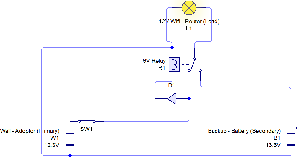
I had build a circuit that can provide current to 12-V wifi-router from two different sources (wall-adapter & battery.)

A 6-V relay is used as switch, to supply power from one of the source at a time.

When wall adapter is on: When Adopter is on

Problems with the Circuit:

1. As 6V relay is powered by 12V adapter, It gets hotter by the time passes(1 hour or more).

2. When primary power (wall adapter) goes off there is tiny-bit delay in supply the power to wifi router so it gets restarted.

What should I do to overcome these problems?

Q1. How do I step down from 12V to 6V, to power the relay.

Q2. What kind of capacitor be use for the short term power in delay time?

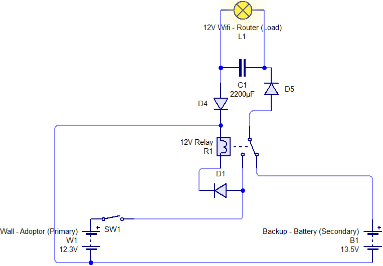
** Upgrade with capacitor & Relay **

  • I have added 2200µF 16V Capacitor with diode, before the Load to ensure power could be supplied for the 2-3~ seconds delay while switching between sources. unfortunately capacitor is powering the Relay instead of wifi-router. what should I do to ensure isolated current to wifi-router?

  • Replace the 6V relay with 12V relay.

enter image description here

Note: I am new to electronics that is why I make circuit as simple as possible. I know I had done some blunders in the circuit. Kindly guide me through.

\$\endgroup\$
13
  • \$\begingroup\$ The correct solution is to use a relay with make before break contacts and a 12V coil along with a diode in the line from the wall adapter. This is obviously not what what you want to hear, since want to stick with your current relay. \$\endgroup\$
    – JRE
    Commented Oct 4, 2017 at 11:20
  • \$\begingroup\$ @JRE Can you elaborate your suggestion? \$\endgroup\$ Commented Oct 4, 2017 at 11:57
  • \$\begingroup\$ Hard to calculate the size of capacitor required without knowing the supply current required by your router. And D1 and D4 serve no purpose, though a diode across your relay coil might be needed to protect your adaptor from back EMF. \$\endgroup\$
    – Finbarr
    Commented Oct 5, 2017 at 12:19
  • \$\begingroup\$ @Finbarr when adapter power goes off, capacitor is powering the relay, thus Relay turn on after a while and capacitor is not doing what its suppose to do (powering the Load). what should I do to stop current flowing to relay?? \$\endgroup\$ Commented Oct 5, 2017 at 19:12
  • \$\begingroup\$ D5 prevents the capacitor from discharging through the relay. D4 and D1 add nothing. \$\endgroup\$
    – Finbarr
    Commented Oct 5, 2017 at 20:17

5 Answers 5

3
\$\begingroup\$

The most common approaches to this kind of buffered (battery backed) power supply are as follows:

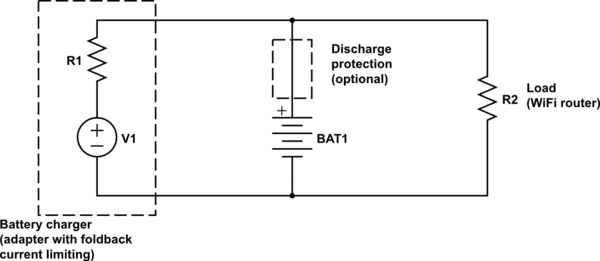
1) Use a power supply (adapter) that is capable of charging the battery, connect it directly to the battery and to the load. Some protection circuitry can be used to disconnect the battery when fully discharged in case of a long power outage. The power supply must have foldback current limiting - to be able to lower its voltage when its current limit is reached. Most adapters restart when overloaded (also known as hiccup mode), which is not suitable. The adapter's max voltage should be selected based on battery type - like 13.8V for a lead-acid battery or 12.3V for 3 Li-Ion in series. The current limit should be enough to supply the load, but not more than the battery's safe charging current. In your case with the WiFi router as a load a 1A limit will be OK with most batteries you could try to use.

schematic

simulate this circuit – Schematic created using CircuitLab

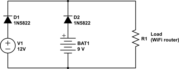
2) Use a power supply with a voltage a bit higher than battery's max voltage and connect them using diodes. This technique can be used in case of a non-rechargable battery. Diodes could be schottky to minimize voltage losses, like 1N5822. D1 could be ommited but the adapter would slightly discharge the battery in case of a power outage.

schematic

simulate this circuit

\$\endgroup\$
3
  • \$\begingroup\$ Another typical answer, I have seen by most of stackexchange Questions. The Answer you have given is not relevant to Questions I ask in detail. As battery has more Voltage then charger I can not charge battery, else it would drain the battery when connected. My question is about using relay as switch in which both power sources are well-disconnect, kindly help me out. \$\endgroup\$ Commented Oct 4, 2017 at 10:40
  • \$\begingroup\$ Todor's #2 solution is the best one. It is referred to as "auctioneering". Yeah, you have a relay, but the fact is you don't need one. To fix your circuit use Todor's solution and put two diodes forward-biased in series with the battery. Their voltage drop will bring battery vdc below the normal supply vdc, which will prevent battery discharge. You will find that your circuit switches so fast you will need very little capacitor to keep the router from resetting - you may be able to do away with the capacitor completely, depending on what the power input circuit of your router is like. \$\endgroup\$ Commented Oct 9, 2017 at 14:50
  • \$\begingroup\$ What if we don't add diode to main 12v power supply. Will it work? I have main 12v Power supply which give 11.3v output after diode and secondary battery which gives 11.2v output. But battery volts drops after sometime. Note: I use external charger to charge battery \$\endgroup\$
    – asad.qazi
    Commented Jun 24, 2021 at 14:01
0
\$\begingroup\$

The simple answer is that you need considerably more capacitance.

Current, capacitance and rate of change in voltage are related by the equation:

\$ I=C \frac{dV}{dt}\$

For a rough guide, let's assume the current consumption doesn't change as the router supply voltage reduces, so with the values you've given of 2 Amps and a drop of 4 Volts (12-8) in 3 seconds you can calculate C using:

\$ 2=C (\frac{4}{3})\$

which gives C = 1.5 Farads. So your 2200uF capacitor (0.0000022 Farads) is well short.

In practice, your router will not be consuming the maximum output of the power supply - probably less than half - so you will probably get away with a mere 750,000uF, but that's still three hundred and forty one 2200uF capacitors in parallel. You may also be able to get away with a shorter maximum time; for instance, 2 seconds instead of 3 will reduce the value needed to 500,000uF.

Perhaps a better way to do this would be to connect a voltage regulator to the battery and set the output half a volt or so below the power supply output voltage. You could then simply combine the battery and supply outputs through a pair of diodes.

\$\endgroup\$
0
\$\begingroup\$

I think the capacitor inside the power adaptor has some contributions on delay of switching. Try modifying the adaptor either by removing or replacing the capacitor with lower uf.

\$\endgroup\$
0
\$\begingroup\$

If it is time to be useful for a doubt not addressed here, let me know, meanwhile I will try to answer your two questions Q1 and Q2 as it goes.

Recommended solution for Voltage Dropout:
I understand you would prefer to focus on the relay solution, that I will discuss ahead, but a short word about the solution to mitigate the short voltage interruption - Using Diodes (regular ones as 1N4004 or Schottky as 1N5822) is the fastest commutation you can have. @Todor answered this very well here, so please see his post.

Relay-based solution:
When PowerSupply (PS) loses power, it takes some time (possibly 0,1 ~ 0.5s) to decay the voltage. Most relays, and yours being 6V rated without further details, will just switch off when voltage drops to about 50% of relay's rated voltage = just 3V in your case. Contact switching time adds 10 ~ 20 ms.

The problem here is that the power source had to drop too much, going down to 3V, then wait that extra time, to become battery energized. So your load/router will receive power from the 13.5V battery too late and the router indeed will restart.

Q1. How do I step down from 12V to 6V, to power the relay?

Q1 & Improving the Relay-based solution:

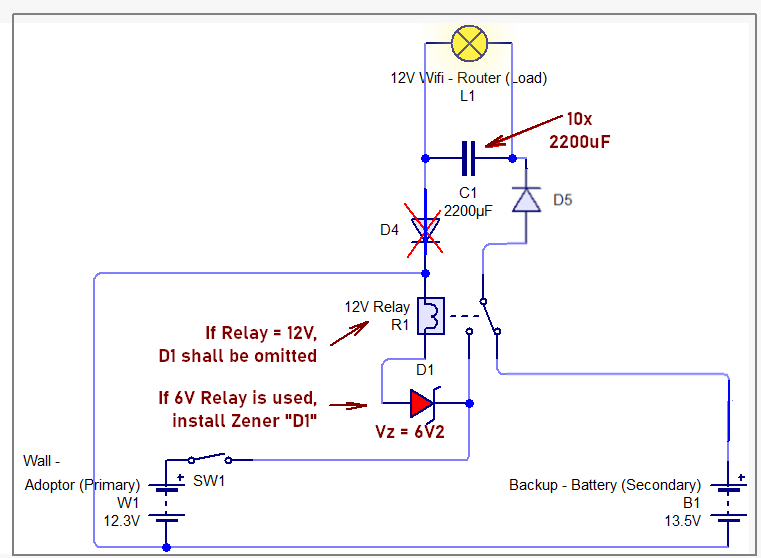
To reduce Heat and preserve service-life in the 6V relay, you could use a Zener Diode to drop the operating voltage. Assuming your relay has not a heavy-duty coil and would consume less than 140 mA @ 6V, then a 6.2V Zener diode as 1N4735A (1W, I.z <= 140mA) could create the voltage drop to make the relay see the 12VDC reduced to 6VDC.
Relay De-energization time: Curiously a 6V Relay with the zener diode will be more than 3x faster now, and probably faster than a 12V relay used at its rated voltage. Now the 6V relay just needs to drop from 12V to 9V, as due to a power outage, would make the relay coil reach 3V at coil much faster, to open the contacts. For a 12V relay, similar decay would need to go as low as 6V.

Q2. What kind of capacitor be use for the short term power in delay time?

Q2 & Capacitor sizing:
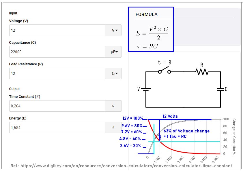
Without further information, I will assume your load/router consumes 1A in 12 V. This gives a load resistance equivalent to R = 12 Ohm. I would consider your marked 2200 uF as an initial guess. Calculation tools as here can show that the time constant is Tau = RC = 26ms. This is not adequate even to compensate for the switching time of the relay. Adopting then 10 units of 2200 uF, we will have Tau = 264ms. See the following picture, where I edited the generated graph:
enter image description here

As can be seen, At T = RC/2 = 130 ms (marked with light-blue vertical line), the voltage decays to ~ 70% Initial voltage, reaching about 7V. Sustaining now for 130ms may be enough holding time if the relay+zener feature is used together. The link and rationale mentioned above will enable you to calculate other values if your actual consumption is different.

Compilation of Circuit comments:
Diode D4 is not necessary and can be omitted and D1 can be replace by that 6V2 zener, polarized backwards (as zener). The updated relay-based circuit would become as follows:
enter image description here

\$\endgroup\$
0
\$\begingroup\$

don't use relay its bad and slowly , just replace relay with P-Channel Mosfet as switch its fast and low consumption power and not need large capcitor to be over the load (Wifi Router) see this below https://www.circuitlab.com/editor/#?id=ns8nu6939k56

have fun :)

\$\endgroup\$

Your Answer

By clicking “Post Your Answer”, you agree to our terms of service and acknowledge you have read our privacy policy.

Not the answer you're looking for? Browse other questions tagged or ask your own question.