1
\$\begingroup\$

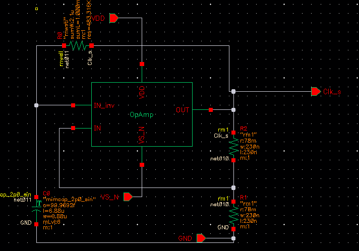
I'm trying to design a clock with 1.8V CMOS. I've designed the Op-amp and individually it works fine (simulated with up to 10MHz pulse input) . But when I use this opamp to draw the feedback circuit , it provides no output.

enter image description here

Output stays tends to zero volts (actually -41 uV ). As there is no desired output,I'v tried many capacitor value and feedback resistor value to see any kind of output pulse, but no luck. As I do not concern with limiting current, current limiting resistor is not used. I even manually give pulse in input to provide startup condition, no luck there either.

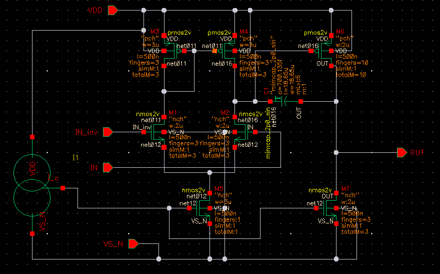
This is my Op-amp circuit: enter image description here

and here is the of Op-amp simulation in 10MHz input pulse at Inverter input. and zero voltage in non inverting input. (Output is not sharp but is more then enough for my use) enter image description here
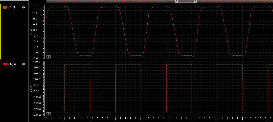
Please, could you give my any suggestion, where could I possibly do wrong? How should I approach next?

thank you for your time.

\$\endgroup\$
3
  • 3
    \$\begingroup\$ A few comments on the screen grab: (1) Turn off the grid before taking the screen grab. The dots make reading unnecessarily difficult. (2) Use an op-amp symbol (triangular) rather than the box. The correct symbols make the schema instantly apparent. The box requires extra work. (3) Use proper ground symbols for ground and eliminate unneccessary ground wires. It removes clutter. (4) There is a built-in schematic editor on the post toolbar. It creates clear black and white schematics very easily and has standard op-amp symbols. \$\endgroup\$
    – Transistor
    Commented Oct 7, 2017 at 9:35
  • \$\begingroup\$ What circuit simulator was this designed in, and what does the symbol with two intersecting circles represent? \$\endgroup\$ Commented Oct 7, 2017 at 17:12
  • \$\begingroup\$ I'm designing this in CADENCE . Two intersecting circles represent 216um constant current source. This current source is mirrored with M5. \$\endgroup\$
    – Anklon
    Commented Oct 8, 2017 at 4:44

1 Answer 1

2
\$\begingroup\$

Your values are surprising; it looks like R1 and R2 are 78 milliohms, which is way too small to make a practical voltage divider. You'd end up pulling your output down to ground too easily. Similarly, C0's 100F is not practical.

If these were ideal components, you'd have a period of 291μS. However, the simulator is going to consider things like the series resistance of components etc, which makes these components not conform to ideals. I know you said you tried with multiple values, but I'd suggest something more practical: for example, tens or hundreds of kiloohms for R1 and R2, and microfarads for C0. Try that, and post your results.

It sounds like you may also have problems with your op-amp. If you designed the op-amp yourself, it may be better to ask what may be wrong with it. For that, we'd need to know the design of the op-amp.

But for the circuit as posted, I'd say that the problem is that R1 and R2 are way too small for any reasonably-designed op-amp to pull into a reasonable range. Additionally, at 100 farads, C0 is going to just act like an open circuit.

You may want to try using a common op-amp, like an LM358 or LM741, in the circuit. Make sure that it works with the values you've chosen. Only after you have that working, put in the op-amp you've designed.

Overall, your circuit topology is correct, but the actual values you're using are going to overwhelm any op-amp design.

\$\endgroup\$
5
  • \$\begingroup\$ Initially I used 10Kohm as R1 and R2. Same result for all cases. for C0. I could not use this high value. My opamp is designed for 2pF capacitance as this is the maximum capacitance value provided in my pdk. \$\endgroup\$
    – Anklon
    Commented Oct 7, 2017 at 9:54
  • \$\begingroup\$ LM741 is likely to be problematic at 10 MHz... \$\endgroup\$
    – user16324
    Commented Oct 7, 2017 at 11:40
  • \$\begingroup\$ @BrianDrummond: and the LM358 is probably even worse (0.7 MHz gain/bandwidth product, vs 1 MHz for the 741). \$\endgroup\$ Commented Oct 7, 2017 at 16:28
  • \$\begingroup\$ I'm not using any chip like LM741 for op-amp. I design this my self and from the output you can see that, it may not work high high precision and sharp edge, but it's capable of providing output oscillation at 10 MHz. Problem occurs when I connect this Op-amp with my RC circuit for self generating pulse. \$\endgroup\$
    – Anklon
    Commented Oct 8, 2017 at 4:46
  • \$\begingroup\$ The capacitance is not 100 farads. The "f" stands for the prefix "femto-" which is \$10^{-15}\$. 100 fF is a very reasonable value to use in an IC design. \$\endgroup\$
    – Dave Tweed
    Commented Feb 15, 2020 at 12:30

Your Answer

By clicking “Post Your Answer”, you agree to our terms of service and acknowledge you have read our privacy policy.

Not the answer you're looking for? Browse other questions tagged or ask your own question.