1
\$\begingroup\$

I'm having troubles with finding the thevenin equivalent in general, particuliary in this circuit:
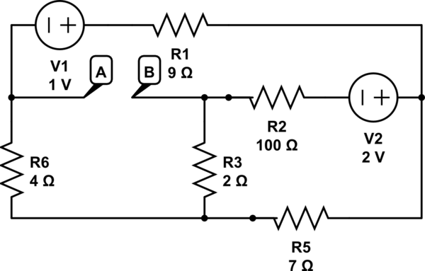
schematic

simulate this circuit – Schematic created using CircuitLab

My question is: how to find the thevenin equivalent considering the load is the one between point A and B?.

Please explain in detail the part of finding Rth. also i would appreciate a method, advice... which would help me to find the Rth in other circuit.

What i have tried: I calculated the Eth by making the load as an open circuit as shown and calculated the current in each branch then i applied the mesh law (KVL) in one of the meshs containing my load which gave me Eth=0.1486Volt. if it's wrong so how to find Eth. If possible, tell some hints before giving the answer.

Any help would be appreciated, thanks in advance.

\$\endgroup\$
2
  • \$\begingroup\$ There are 210 questions on Thevenin theorem on this website plus huge huge resources, worked examples, etc. available online. Tell me why they didn't help you figure out your problem. \$\endgroup\$
    – dirac16
    Commented Oct 13, 2017 at 10:45
  • \$\begingroup\$ @dirac16 have read many of them but that doesn't necessarily mean that i would be able to solve this one (they are in genral very different than this case). Anyway i have found your comment helpful, maybe looking for more examples will help. \$\endgroup\$
    – Mehdi
    Commented Oct 13, 2017 at 11:04

1 Answer 1

1
\$\begingroup\$

There are several ways to reduce a net of sources and resistors to its Thevenin equivalent. One way is like what you started to do. Find the open circuit voltage and the short circuit current.

Another way is to keep simplifying the circuit in steps. Take a source and two resistors and find its Thevenin equivalent on its own. Then replace the three parts with the two Thevenin equivalent parts in the circuit. Keep doing this until the circuit is a single voltage source in series with a single resistor.

However, in all cases you should start by drawing the circuit in a comprehensible way. Problems like this are often deliberately drawn to obscure the circuit. Never let that get in your way. Redraw the schematic properly with power voltages descending down the page, logical flow left to right, etc. That should be your first step here too.

You should always draw circuits properly before asking others to look at them. This web site is no exception.

\$\endgroup\$
1
  • \$\begingroup\$ Firstly i see that R5 and R4 are in parallel, if so where to plugin the new equivalent resistance (R5//R4) and if no so they are in series (assuming two dipoles are either in parallel or in series), so where to plugin the new equivalent resistance (R4+R5), same for R4 and R3, can you please clarify if possible?. \$\endgroup\$
    – Mehdi
    Commented Oct 14, 2017 at 8:47

Your Answer

By clicking “Post Your Answer”, you agree to our terms of service and acknowledge you have read our privacy policy.

Not the answer you're looking for? Browse other questions tagged or ask your own question.