1
\$\begingroup\$

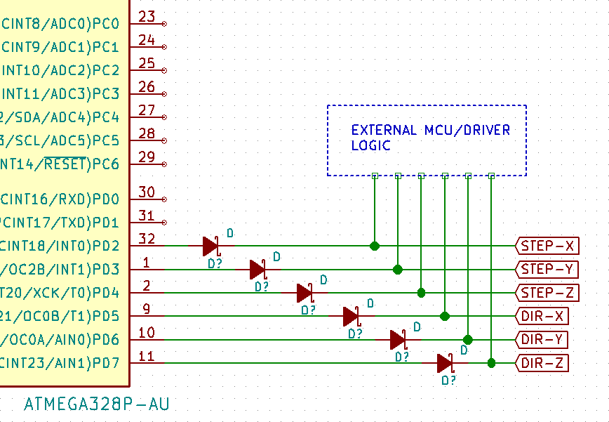
I have an Atmega328P MCU that is driving a stepper motor driver using its digital I/O. However, I'd like to use the same pins to drive the motor externally as well possibly using a different MCU or hardware. When the external driver is driving the motor using these same pins, the Atmega328P MCU maybe powered down and its state would be unknown. I know that its not safe to drive the Atmega328P MCU's pins with logic levels when its powered down and it will in fact destroy the chip.

To overcome this, I thought of adding low power Schottky diodes between the Atmega328P MCU's pins and the motor driver inputs (as shown in the image). Would this be ok or can any one recommend a better solution? I know I could use an optocoupler but I do not space on the board for placing so many of them.

enter image description here

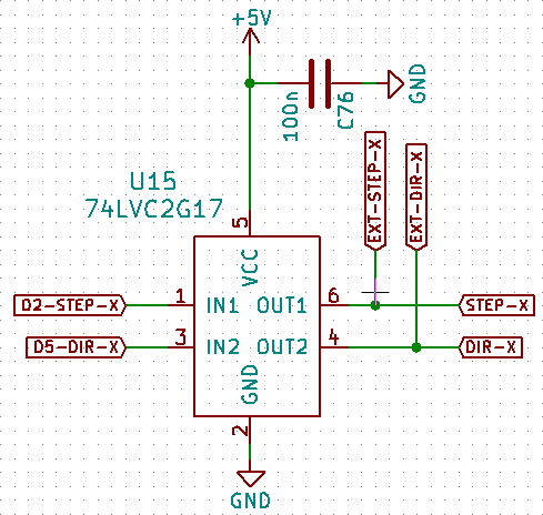
UPDATE: This is what I'm finally thinking of doing (see image). The buffer chosen here can sustain upto +6.5V on its output terminals when powered down. I also realized that even when an external logic control is used, the board still has to be powered on for the motor drivers to work. This means that the onboard Atmega would also be powered on. However there is the possibility of the user inadvertently forgetting to power on the board before plugging in an external control source. In this case the onboard Atmega would experience 5V on its I/O pins when its powered down which obviously is not good. These buffers take care of that.

enter image description here

\$\endgroup\$
6
  • \$\begingroup\$ I think you want a tri-state buffer. When the Atmega is active, it can drive high or low, when you want it to go inactive, its outputs go high-Z. \$\endgroup\$
    – Wesley Lee
    Commented Oct 13, 2017 at 14:40
  • \$\begingroup\$ @WesleyLee You are suggesting I use tri-state buffers instead of the diodes? They usually have a control input that sets the state of the pins and this means more software logic that I'm not particularly keen on right now. I was hoping I could solve this using only hardware. \$\endgroup\$ Commented Oct 13, 2017 at 15:01
  • \$\begingroup\$ Shottkys tend to have bad reverse leakage. You don't have room for optocouplers, but do you have room for small MOSFETs? \$\endgroup\$ Commented Oct 13, 2017 at 15:24
  • \$\begingroup\$ @evildemonic How would I do the isolation using MOSFETs? \$\endgroup\$ Commented Oct 13, 2017 at 16:02
  • \$\begingroup\$ Gate to the I/O on your AVR, source to ground, pull the drain high with a resistor to your positive rail. Take your output from between the resistor and the drain. Note that your signals from the AVR will now be inverted. \$\endgroup\$ Commented Oct 13, 2017 at 16:24

2 Answers 2

4
\$\begingroup\$

I would use a dual supply level translator such as 74LVC8T245.

As stated in the datasheet, when either VCCA or VCCB are at the GND level, both ports are at high impedance (i.e. disconnected). Therefore you can connect, say, VCCA to your ATMEGA328's VDD, so when it's powered down, no problem will occur.

You can also tristate the outputs by pulling OE high. In this way you can have your circuit automatically pulling OE high when you are connecting an external driver, to avoid contentions.

All inputs can accept 5.5V regardless the VCC voltage, and, as a bonus fact, you can also use a VCCA value different from the VCCB.

\$\endgroup\$
3
  • \$\begingroup\$ This is very interesting. If my data direction were to be from An to Bn, then I'll have to connect my Atmega's pins to An and then the external driver logic inputs go to Bn and then Bn pins also go to the motor driver. I'm getting it right? \$\endgroup\$ Commented Oct 13, 2017 at 19:51
  • \$\begingroup\$ Yes! By the way, OE and DIR signals are referenced to VCCA, so maybe in some cases you might want to use the B port for the ATMEGA, and the A port (always powered) for the external controller + external driver logic inputs. \$\endgroup\$
    – next-hack
    Commented Oct 14, 2017 at 6:55
  • \$\begingroup\$ Kinda using your idea but with a different device. Thanks for suggesting this. \$\endgroup\$ Commented Oct 15, 2017 at 16:05
0
\$\begingroup\$

The issue you have here is you really need to remove the ATMEGA drive completely when driving with the external source, and vica versa. No diode matrix will do that for you for all permutations of outputs and power configurations.

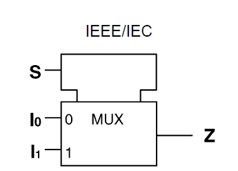
As such it would be prudent to add 2:1 multiplexers, or equivalent logic, to each signal so that the controller outputs are fed explicitly from one or the other.

enter image description here

You can select which controls are enabled by a number of methods.

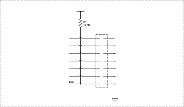
  1. Configure the connector to the external source to include a pin that is jumpered in the cable to force the mux into the appropriate state. That way, plugging in the cable will automatically allow the external control through to the driver. Optionally, this control pin could also be wired to a switch somewhere if this is to be wired permanently within an enclosure of some sort.

schematic

simulate this circuit – Schematic created using CircuitLab

  1. Use a pin from the atmega to select the channel... with appropriate pullups to select the appropriate channel when the atmega is powered off.
  2. Add a dip-switch, or jumper to manually configure the routing.
\$\endgroup\$
7
  • 1
    \$\begingroup\$ Only option 2 seems viable, and in all probability you then would NOT power off the ATMEGA328 ... as you need the VCC to run you pullups. \$\endgroup\$ Commented Oct 13, 2017 at 15:42
  • \$\begingroup\$ @JackCreasey yes, it really depends on how he plans on implementing the second source, whether it is a backup system, something permanently wired, etc. It could even be selected from a control signal from the backup system if need be. With no further info in the question, options are varied, but logic isolation is warranted. \$\endgroup\$
    – Trevor_G
    Commented Oct 13, 2017 at 15:52
  • \$\begingroup\$ Thank you. MUX's make sense but again I'm constrained by space on the board. Even single channel ones would require decoupling caps and all that would need more space than I can give at the moment. Option #3 makes the most sense to me if I were to go this route. The idea was to allow the stepper drivers to be controlled using the Atmega loaded with say grbl but also have the ability to control the drivers using say Mach3 via an isolated parallel port. \$\endgroup\$ Commented Oct 13, 2017 at 16:01
  • \$\begingroup\$ @electrophile pretty much any on-board solution will be problematic if you have no space. If the step rates are reasonably slow and you have six available pins on the atmega you could consider channeling them through the latter. That is have the atmega pass on the external drivers control signals if the delay is acceptable. \$\endgroup\$
    – Trevor_G
    Commented Oct 13, 2017 at 16:10
  • \$\begingroup\$ @electrophile if it's an either or solution, and you have room, a simple three by six jumper block might be sufficient. \$\endgroup\$
    – Trevor_G
    Commented Oct 13, 2017 at 16:24

Your Answer

By clicking “Post Your Answer”, you agree to our terms of service and acknowledge you have read our privacy policy.

Not the answer you're looking for? Browse other questions tagged or ask your own question.