1
\$\begingroup\$

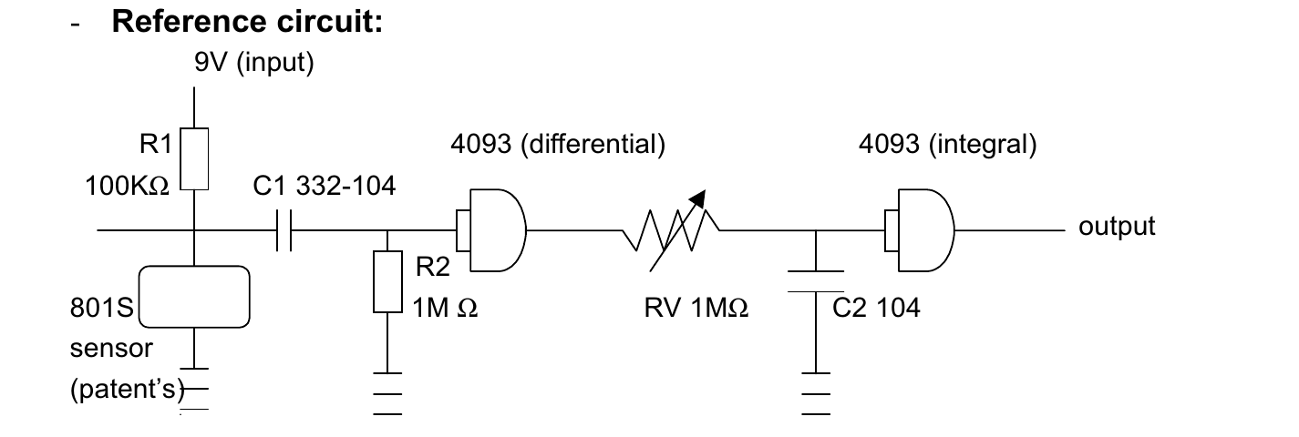
I have attempted this diagram from here:

enter image description here

with one modification - instead of the 4093 circuit ( comparator+inverter+hysteresis gates) I have used a HC14 (inverter+hysteresis gates). Can this be why i am not seeing much difference when varying the pot ? Tried with 3 values for C1 - 3.3, 10 and 100 nF. It doesn't seem to make any difference as to how sensitive the circuit is. The output is connected to a MCU pin which interrupts on all changes and blinks a led.

Also, I don't quite understand the bottom two notices from that pdf:

Attention:

  1. The point of output must become square wave. (cannot use as shock switch)
  2. Take low or high of output square wave into your alarm system and adjust sensitivity from the delay time length

I should say that another breakboard of this same sensor works much better by adjusting the trimpot - this one

update

I have read the raw analog output right from the sensor's pin and plotted both the dev board readings and my own PCB readings on the same graph. The dev board readings are much quieter than the readings from my PCB. Maybe the weight of the board and its cables are the main cause in the outputs difference ?

\$\endgroup\$
4
  • \$\begingroup\$ i am not seeing much difference when varying the pot ? what difference to you expect to see when you vary the pot? From looking at the circuit I think the pot just sets the time delay before the output responds and stops responding to shaking of the sensor. \$\endgroup\$ Commented Oct 16, 2017 at 8:59
  • \$\begingroup\$ What is the power supply voltage for the 74HC14, pin Vcc? \$\endgroup\$
    – Steve G
    Commented Oct 16, 2017 at 9:01
  • \$\begingroup\$ @Bimpelrekkie I would expect the led to flicker more / less as I turn the trimmer. Seems it flickers about the same. The vibration source is a diesel engine idling in all cases. \$\endgroup\$
    – kellogs
    Commented Oct 16, 2017 at 9:35
  • \$\begingroup\$ @SteveG Ah, forgot about that - it has changed too, I am using 3.3 V everywhere \$\endgroup\$
    – kellogs
    Commented Oct 16, 2017 at 9:35

2 Answers 2

1
\$\begingroup\$

Not a real answer but it might help someone. This circuit here works - https://youtu.be/dKKD8qsL1dM?t=412

\$\endgroup\$
0
\$\begingroup\$

What you are controlling with that adjustable resistor is the speed the C2 capacitor is filled and emptied through the output stage of the left Schmitt trigger inverter.

If the left Schmitt trigger is changing its output stage fast (high-pitch noise), that adjustable resistor makes no difference, the C2 cap will be never full enough to have the right Schmitt trigger change its output state.

You need to change the high pass on the left first. It has to be adjusted low enough so the left Schmitt trigger reacts to rumbling, too.

\$\endgroup\$
1
  • \$\begingroup\$ Hmm, okay, but I have also tested the circuit with hand strokes in case those produce other frequencies - same deal. I have already changed the C1 cap twice as per the original question. \$\endgroup\$
    – kellogs
    Commented Oct 16, 2017 at 16:22

Your Answer

By clicking “Post Your Answer”, you agree to our terms of service and acknowledge you have read our privacy policy.

Not the answer you're looking for? Browse other questions tagged or ask your own question.