0
\$\begingroup\$

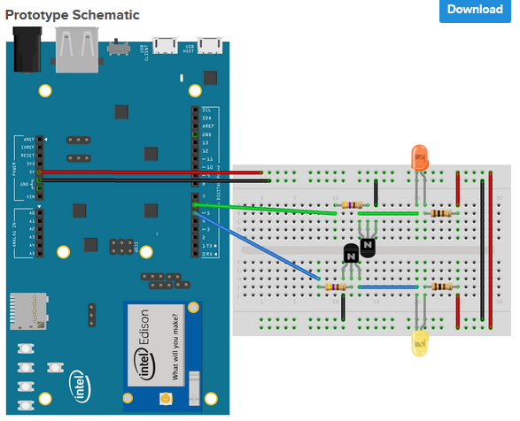
i'm starting get into designing some IOT devices for around the house and looking other peoples design on Hackster.io. I've come across several designs that i'm having a hard time understanding. The below picture to me doesn't make sense. My understanding is the the electric flow starts with positive and flows to the negative. On the below picture for example we see GPIO pin 5 (blue wire) connects to resister then flows to the transistor then to the blue wire though the negative side of the led.

I don't know understand how this works since we would need current to flow through the resister then LED. When the developers code execute whatever on GPIO5, isn't this flowing the wrong way? I will go out and say i'm starting at the bottom with basic understand if that.

enter image description here

\$\endgroup\$
4
  • 10
    \$\begingroup\$ That's not a schematic! \$\endgroup\$
    – winny
    Commented Oct 18, 2017 at 16:24
  • \$\begingroup\$ The blue wire is connected to the base. While the LED is connected to the collector (probably). \$\endgroup\$
    – Eugene Sh.
    Commented Oct 18, 2017 at 16:26
  • \$\begingroup\$ Please learn to use the schematic tool on this site it is very good. Also can you label the schematic with circuit references e.g. R1, R2, Q1 etc and if you have them values. It is much easier to explain how a circuit works with this information. Personally I wouldn't have bothered to work out what your circuit is from this diagram but others have. They will be much less keen to do so as you start asking about more complex circuits. Also what are the transistors people have guessed that they are small signal NPN transistors and also assumed it is a particular common pin-out. \$\endgroup\$ Commented Oct 18, 2017 at 17:03
  • \$\begingroup\$ Thanks for your comments and pointing out the difference. I'll check our the schematic tool and play around with it. Thanks again. \$\endgroup\$
    – Adam
    Commented Oct 18, 2017 at 18:00

3 Answers 3

2
\$\begingroup\$

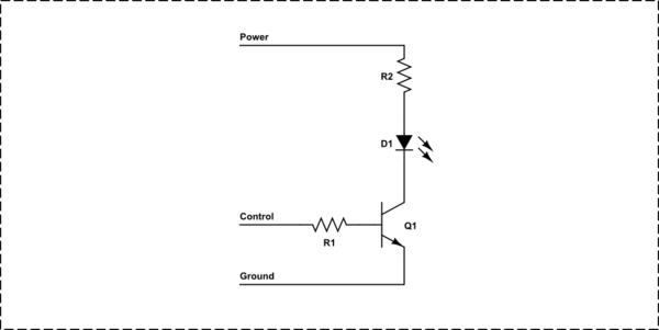
Here is one channel of your circuit in schematic form.

schematic

simulate this circuit – Schematic created using CircuitLab

When the control signal from the micro is high, current flows into the base of Q1 and is limited by R1. This causes current to flow into the top, the collector, of Q1 effectively turning it on. As such current will flow from the power supply through the current limiting resistor R2 and the LED which will light.

When the control signal is pulled to ground, no current will flow through R1 into the base of Q1 so the transistor turns off as does the LED.

\$\endgroup\$
5
  • \$\begingroup\$ Thanks Trevor! This helped me understand how the LED lights. So if I understand this right, power is running through R2 and D1 all the time but the LED is not powered on because Q1 is pushing this current to group. But Once high is set on on the control wire, the electricity meets in the top of Q1 thus completing the circuit? \$\endgroup\$
    – Adam
    Commented Oct 18, 2017 at 18:09
  • \$\begingroup\$ @Adam almost. The voltage is present all the time.. not the current.. Q1 acts like a switch operated by the control signal. When the switch is open there is no current in R2 and D1. \$\endgroup\$
    – Trevor_G
    Commented Oct 18, 2017 at 18:13
  • \$\begingroup\$ Ugh oh, this might of lost me. I understand this is all theory based but does't power flow from + to -? There for power will always be running through R2 and D1 but is grounded out until Q1 is activated via the HIGH command? Everything you said would of made sense if the flow went from Q1 to Power, but I think my struggle now is understanding the flow of the voltage (not current :)). Thanks again for taking time to help. \$\endgroup\$
    – Adam
    Commented Oct 18, 2017 at 19:11
  • \$\begingroup\$ @Adam power and current only flows if there is a complete circuit. That is, no opening in the circuit. When you add a switch (In this case a transistor), the circuit is not complete when the switch is open. In reality though, when off, the transistor is just a REALLY LARGE resistor. So current is almost nothing. BUt don't think about that too much.. it will just confuse you. \$\endgroup\$
    – Trevor_G
    Commented Oct 18, 2017 at 19:18
  • 1
    \$\begingroup\$ Got it! Closing the circuit will allow flow. This has been great. Thank you very much! \$\endgroup\$
    – Adam
    Commented Oct 18, 2017 at 19:27
3
\$\begingroup\$

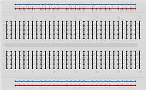
So there is a big difference between a bread board and a schematic. The breadboard has internal connections that don't span the columns.
enter image description here

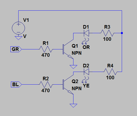
As for what this would look like if it were a schematic, it is fairly simple. enter image description here

You are using the wired inputs to control the transistor as a switch. This allows for greater current to flow through to the led to give you light from your power supply.

Remember that a picture of a breadboard is not a schematic, it is how the highway system looks when implemented. The schematic is the roadmap, and although the roads layout can be different (breadboard, pcb, etc), you still will get to the destination.

\$\endgroup\$
2
  • \$\begingroup\$ Thank you for helping out on this. I see how you created the schematic and it actually really helped me understand. That might be part of my confusion when trying to understand is the schematic doesn't appear to be the same as the bread board, but your explanation helped me. Thank you again! \$\endgroup\$
    – Adam
    Commented Oct 18, 2017 at 18:03
  • \$\begingroup\$ In my personal opinion I feel that it is always much better to start with the schematic then with the breadboard. I am happy my explanation could help you, keep dreaming and building! \$\endgroup\$ Commented Oct 18, 2017 at 18:41
0
\$\begingroup\$

Transistor circuits still contain loops for current to flow through. See here for a diagram that may illustrate this better. In your example, when GPIO 5 is brought high, current will flow out of it, through the resistor, through the base to the emitter in the transistor, to ground. This will cause current to be allowed to flow from the collector to the emitter, making a second loop - current will flow out of the source (the Arduino 5V), through the second resistor, through the LED, through the collector-emitter path in the transistor, to ground.

\$\endgroup\$
2
  • \$\begingroup\$ Billy, this answered my question I just asked Trevor. Thank you! should of read your response because responding above. Everyone here has been great, thank you for the quick lesson. \$\endgroup\$
    – Adam
    Commented Oct 18, 2017 at 18:11
  • \$\begingroup\$ My pleasure! If this helped you, it would really help me if you could accept my answer. \$\endgroup\$ Commented Oct 18, 2017 at 18:12

Your Answer

By clicking “Post Your Answer”, you agree to our terms of service and acknowledge you have read our privacy policy.

Not the answer you're looking for? Browse other questions tagged or ask your own question.