0
\$\begingroup\$

I am trying to see if I understand how impedance works correctly before I build this into a real circuit. Basically I have an inductor (helmholtz coil) driven by a function generator, now by itself we know the higher the freq goes the lower the current the coil will receive. If my understanding is correct, I can put a capacitor in parallel with the coil, which would mean at higher frequencies the Xc would decrease and Xl would increase, but since they are in parallel Xtot should decrease, thus as a result you will get a higher current at the same frequency than if we had just had a inductor (coil) in the circuit by itself. Is this understanding correct? Or is there a smarter way to increase the current my circuit receives at a higher frequency, besides increasing the current outputed by the generator/changing the coil design itself.

p.s. this is a re-expression of the question asked here Impedance for Helmholtz Coil Connected to Audio Amplifier but in a more detailed and precise way I hope

\$\endgroup\$
8
  • \$\begingroup\$ Looking at my question I think I just asked some variation of what would be the best way to do impedance matching for a higher frequency and thus deliver a higher current, than if I had poor matching? I guess the real concern is to make sure that the resistor or capacitor can withstand the current/power sent through it - since the inductor can \$\endgroup\$
    – eWizardII
    Commented Jun 9, 2012 at 4:36
  • \$\begingroup\$ You possibly trying to stretch the Ohms law with resistance networks into area where impedance is not just an active resistance anymore, but also a reactance. Try the same formulas for parallel networks and you will discover a case with division by zero: infinite impedance to resonant frequency. \$\endgroup\$
    – user924
    Commented Jun 9, 2012 at 16:58
  • \$\begingroup\$ Okay, so maybe want I want to do is instead just add another coil in parallel? Like a choke or something which would then lower the impedance at higher frequencies? Instead of bothering with R and C elements. \$\endgroup\$
    – eWizardII
    Commented Jun 9, 2012 at 19:13
  • \$\begingroup\$ I think you are overanalyzing the problem. The impedance of a speaker is typically very much an active resistance because it is a sort of mechanically loaded motor. Surprizingly there might be no much inductance component in a load. The fall at high frequencies might be caused more by mechanics and less by inductance. \$\endgroup\$
    – user924
    Commented Jun 9, 2012 at 19:21
  • 1
    \$\begingroup\$ Yes. You understood it exactly for unloaded coil (loop antenna loaded to impedance of infinite empty space ~300 Ohm of vacuum or air). The situation will change if you place a screwdriver into coil opening or frozen frog wrapped into gold leaf or whatever you do withing your experiment. You are not just emitting ultra low frequency radio. But who knows. \$\endgroup\$
    – user924
    Commented Jun 9, 2012 at 19:49

1 Answer 1

3
\$\begingroup\$

"since they are in parallel Xtot should decrease"

That's not automatically true for complex impedances. For the inductor \$Z_L = j\omega L\$, for the capacitor \$Z_C = \dfrac{1}{j \omega C}\$. Both in parallel gives

\$ Z = \dfrac{j\omega L \cdot \dfrac{1}{j \omega C}}{j\omega L + \dfrac{1}{j \omega C}} = \dfrac{j\omega L \cdot \dfrac{1}{j \omega C}}{\dfrac{j^2 \omega^2 LC + 1}{j \omega C}} = \dfrac{j\omega L}{1 - \omega^2 LC} \$

The minus sign in the denominator is interesting. Since \$\omega^2 LC\$ is positive, we can find a value for it where the denominator becomes zero.

\$ \omega^2 LC = 1\$

or

\$ \omega = \sqrt{\dfrac{1}{LC}} \$

If the denominator is zero the impedance is infinite. That goes against intuition which says that paralleling two components will give a lower impedance than the lowest of the two.

enter image description here

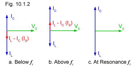
The image gives the explanation. Currents through \$C\$ and \$L\$ are at 90° with voltage, but in opposite directions. If their magnitudes are different their sum will be either a capacitive or inductive current. But when they're equal the sum is zero. No current. A zero current for a non-zero voltage means infinite impedance.

The frequency for which this is true is the resonance frequency, and it's used to make oscillators and high-Q filters.

\$\endgroup\$
3
  • \$\begingroup\$ Thanks - Based on my amplifier that would output 63V (2000 W into 2 ohms), I did \$X_{tot} = X_l X_c / (X_c + X_l)\$ where I have a .01059 Henry coil and a 1.8 uF capacitor in parallel. From this I solve for frequencies between 0 and 50 kHz, resonance will occur at 940 Hz. Wolfram Alpha Calculation Does that sound correct given the circuit setup though? \$\endgroup\$
    – eWizardII
    Commented Jun 9, 2012 at 17:53
  • \$\begingroup\$ Though for above \$f_r\$ does \$I_l\$ continue to drop? Because that's what I am trying to prevent from happening. \$\endgroup\$
    – eWizardII
    Commented Jun 9, 2012 at 18:01
  • \$\begingroup\$ Okay I may understand it what I would want to do is put the resonance frequency as high as possible because anything below it would behave like a inductor which is where I want the max current, where as when I pass resonance the circuit becomes capacitive which is not what I want. Maybe? \$\endgroup\$
    – eWizardII
    Commented Jun 9, 2012 at 18:14

Your Answer

By clicking “Post Your Answer”, you agree to our terms of service and acknowledge you have read our privacy policy.

Not the answer you're looking for? Browse other questions tagged or ask your own question.