0
\$\begingroup\$

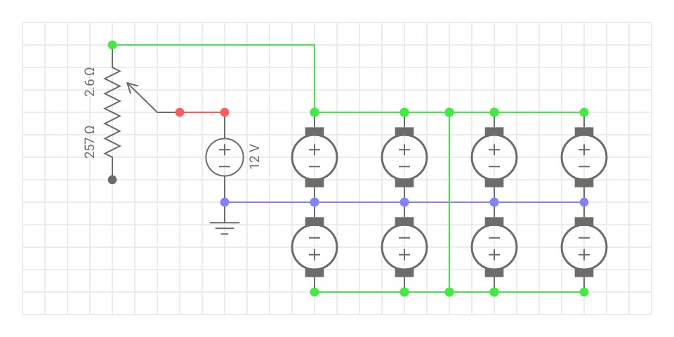
Someone mentioned to me that they wanted to replace a fan switch with a potentiometer to adjust the fan speed. This seemed a reasonable request, and being eager to learn, I drew up a schematic using a simulator (colour has been used to avoid any confusion).

It went from this: switch Switch.

To this: potentiometer Potentiometer.

The circuit appeared to work, but got laughed at because, "Running 600mA through a potentiometer is not a good idea." and, "A waste of a good pot."

So I read about it, and (without really finding an explanation as to why) I discovered that a transistor is typically required. This seems weird to me because I was under the impression that transistors were much more sensitive than potentiometers, and easier to ruin.

Anyway, I tried implementing a transistor. No doubt there are better (more sophisticated, more components, etc.) circuits for achieving the same goal, but for now I just wanted to make sure I was using the transistor correctly:
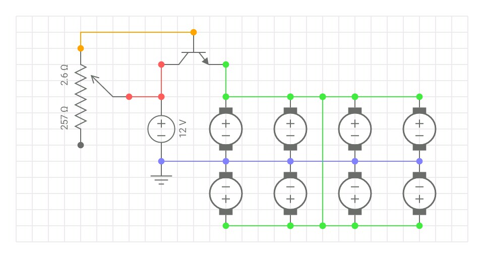
potentiometer+transistor Potentiometer + NPN Transistor.

My understanding is that the potentiometer now controls the transistor, rather than the fans directly. And the transistor is basically like a variable gate between the fans and their power source.


The Result: Current across the potentiometer has dropped from 600mA to 6mA, but the maximum fan speed/RPM has dropped by ~50%.

\$\endgroup\$
3
  • 1
    \$\begingroup\$ Tip: add the Watt rating of the fans. And possibly what make and model you have of the NPN and potentiometer. \$\endgroup\$
    – Dejvid_no1
    Commented Oct 22, 2017 at 10:53
  • \$\begingroup\$ @Dejvid_no1 It doesn't really seem relevant to the actual question, so I left it out for the sake of simplicity. This is just one example. But for arguments sake, I was working with a hypothetical value for the fans: 12V 100mA. As for the transistor, I don't have/know the specific model; its just a generic, default transistor used by the software (EveryCircuit). \$\endgroup\$
    – voices
    Commented Oct 22, 2017 at 11:05
  • \$\begingroup\$ Also, at this stage, the potentiometer has no model either. It's just a hypothetical, generic 260Ω variable resistor. The question is really about the correct use of a transistor in this, or a similar situation. Specific values surely change from circuit to circuit, but I imagine the general concept remains the same; like for a lighting dimmer switch, for example. So, correct me if I'm wrong, but this is really just one of many examples I could have chosen, to give some context for the question. \$\endgroup\$
    – voices
    Commented Oct 22, 2017 at 11:22

2 Answers 2

1
\$\begingroup\$

You need a PNP transistor for the high side switch. Your circuit only "works" because current flows across the BE diode - it is forward based after all.

Remember that for an NPN transistor, the base must have a potential of ~0.7V above the emitter, which is only possible in your circuit when CE resistance is high enough.

\$\endgroup\$
4
  • \$\begingroup\$ Okay, that doesn't seem right. And I got confusing results with a PNP transistor. But you probably know better than I. If that's the case, the question remains, however: The correct configuration is... If you can show the correct configuration, and it works, I'll mark your answer correct. \$\endgroup\$
    – voices
    Commented Oct 22, 2017 at 11:34
  • 1
    \$\begingroup\$ The PNP will need its base resistor connected to 0V, and the emitter connected to 12V. The load is at the collector. \$\endgroup\$
    – Turbo J
    Commented Oct 22, 2017 at 11:36
  • \$\begingroup\$ I didn't know that re: ~0.7V, by the way. Also, what is BE & CE? \$\endgroup\$
    – voices
    Commented Oct 22, 2017 at 11:37
  • \$\begingroup\$ A potentiometer is also a resistor. You should not use just a potentiometer because the potentiometer would generate more heat than it could dissipate, and the potentiometer would "fry". \$\endgroup\$
    – mguima
    Commented Oct 22, 2017 at 12:52
1
\$\begingroup\$

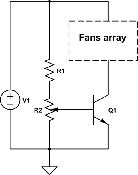
In both cases (a potentiometer and a transistor), a compensation voltage regulation method is used. Which leads to significant dissipation of heat if not on a potentiometer, then on a transistor.

It is better to use pulse width (PWM) regulation.

PS: To simulate the case with a transistor can be as follows:

schematic

simulate this circuit – Schematic created using CircuitLab

\$\endgroup\$
2
  • \$\begingroup\$ The circuit drawed above by AltAir is simple and efective. But use a power transistor because the transistor may get hot, that's why a PWM should be used instead. I would add just an advice to the OP: if you use this circuit, or even if you use a PWM, have in mind that most of motors can't be controlled in a linear way, especially if they weren't designed for this. Expect to be able to control the motor only in the 40%-100% range of the maximum speed, 20%-100 if you have luck. \$\endgroup\$
    – mguima
    Commented Oct 22, 2017 at 13:04
  • \$\begingroup\$ Another nitpick: This circuit will not work if the fans have a speed sensor output connected. You will need a high side transistor in this case. \$\endgroup\$
    – Turbo J
    Commented Oct 22, 2017 at 14:02

Your Answer

By clicking “Post Your Answer”, you agree to our terms of service and acknowledge you have read our privacy policy.

Not the answer you're looking for? Browse other questions tagged or ask your own question.