0
\$\begingroup\$

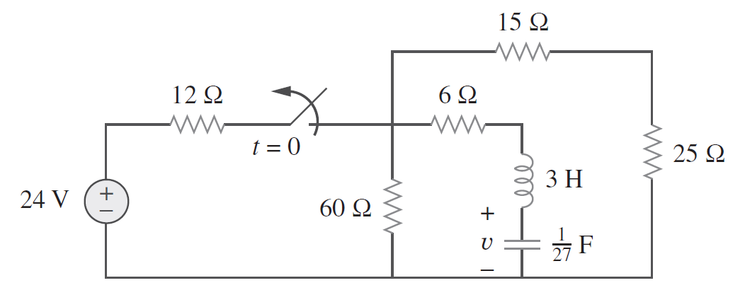
I've got this circuit. It contains a switch that will open at T = 0:

I'm tasked with finding the voltage on the capacitor. I calculate the initial conditions (assuming that the capacitor and the inductor are fully charged). The initial C voltage is 16 V and the initial current through the inductor is 0 A.

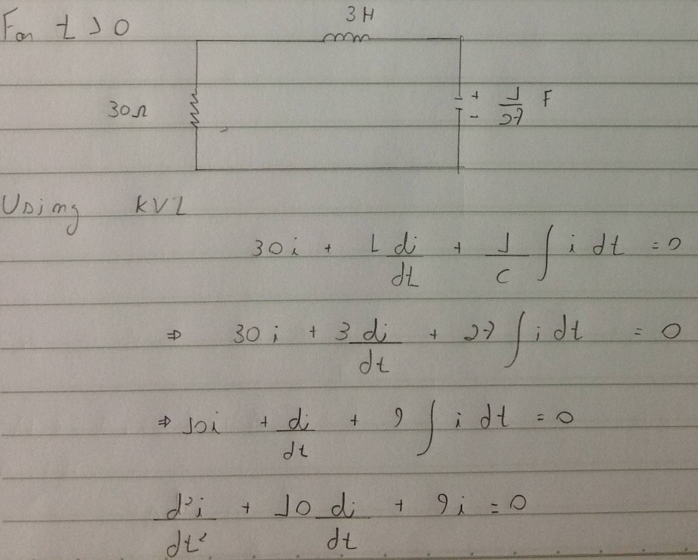
Then I proceed to simplify the remaining components and I get to this circuit:

schematic

simulate this circuit – Schematic created using CircuitLab

Then I want to apply Kirchoff's Voltage Law. I get this equation:

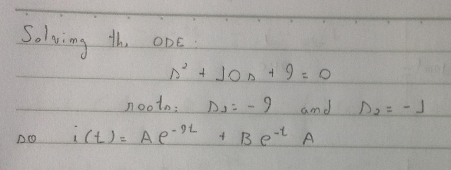
And solving for the ODE (without the constants):

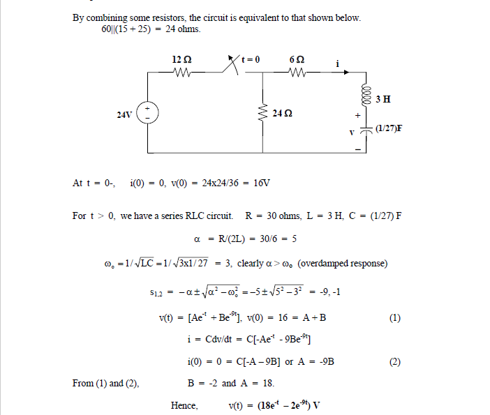
However, according to the solution manual, this equation describes the voltage in this circuit. How can that be? I can't understand the gap between having the ODE and its correlation to the voltage. Here is the solution:

\$\endgroup\$

1 Answer 1

1
\$\begingroup\$

Whatever you did is correct. You have got an expression for current. Solution manual has used a different approach and they have obtained expression for voltage.

Finally what you want is voltage. Let's start from where you have stopped.

$$i(t)=Ae^{-9t}+Be^{-t}$$

so voltage across capacitor: $$\begin{align*} v(t)&=\frac{1}{C}\int i(t) dt\\ &=-27\left[\frac{A}{9}e^{-9t}+Be^{-t}\right] \end{align*}$$

Now we have to evaluate the constants \$A\$ and \$B\$. From the initial conditions, you know that \$i(0^-)=0\$ and current through an inductor can not vary instantly. Which gives: $$0=A+B\tag1$$

Now we need one more condition. We know that voltage across capacitor can not vary instantly, and \$v(0^-)=16\$.

$$16=-3A-27B\tag2$$

From (1) and (2) you can solve for \$A\$ and \$B\$. You will get the same answer as given in solution manual once you submit these values to voltage expression.

\$\endgroup\$

Your Answer

By clicking “Post Your Answer”, you agree to our terms of service and acknowledge you have read our privacy policy.

Not the answer you're looking for? Browse other questions tagged or ask your own question.