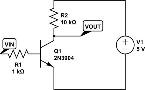
How can I calculate the slew rate and bandwidth of a typical transistor amplifier such as the following? What are the parameters I need to consider?

simulate this circuit – Schematic created using CircuitLab
How can I calculate the slew rate and bandwidth of a typical transistor amplifier such as the following? What are the parameters I need to consider?

simulate this circuit – Schematic created using CircuitLab
To compute the dynamic response of this circuit, you can use the hybrid-pi model to which you add a parasitic capacitance between collector and base. This is a 1st-order circuit and be solved in a variety of ways. I used the fast analytical techniques described here. First, I determine the dc transfer function, \$H_0\$, for which I open the capacitor. Then, I will determine the resistance "seen" by the capacitor when the excitation \$V_{in}\$ is reduced to 0 V (replace the source by a short circuit in the schematic). Finally, I will determine the resistance "seen" by the capacitor when the output is nulled with the excitation back in place. The below diagram shows all these steps:
Each resistance associated with a capacitor forms a time constant. For a 1st-order system, the pole is the inverse of the natural time constant. When you determine the zero, you realize that this is a right-half-plane zero and distorts the phase response. When you assemble all results, you have
\$H(s)=H_0\frac{1-\frac{s}{\omega_z}}{1+\frac{s}{\omega_p}}\$ with:
\$H_0=-\beta\frac{R_2}{R_1+r_\pi}\$ \$\omega_p=\frac{R_1+r_\pi}{C_1(R_1R_2(\beta+1)+r_\pi(R_1+R_2))}\$ \$\omega_z=\frac{\beta}{C_1r_\pi}\$
Plotting the whole thing with Mathcad gives you the dynamic response you need:
Now, regarding slew-rate, I am not sure the term fits this circuit. We usually identify slew-rate when the rate-of-change of the input signal of an op amp unbalances its differential bipolar input and the output cannot follow the input slope (see here). With a simple circuit like here, it is more about the rise time you can obtain I believe when you step the input. Considering the high-frequency zero and the low-frequency pole incurred by the capacitor, the rise time can be approximated as \$t_r\approx 2.197\tau=75\;\mu s\$ as given here. \$\tau\$ is the inverse of \$\omega_p\$. This is an approximation but as the zero is really high, it works ok as shown in the below sim where the input is stepped from -10 to -20 mV:
We'll compute the slewrate when Vce is 2.5 volts.
At that operating voltage, Ic is 2.5/10k or 0.25mA.
GM (transconductance) at 0.25mA is 1/(0.026 / 0.00025) = 1/39*4 = 1/156 ohms
Gain is 10kohm / 156 ohm or 10 * 6 = 60x
The Cmiller is 10pF (Cob) * (1 + 60) ~ 10pF * 60 = 600pF.
The input timeconstant is Rbase * 600pF = 600,000 picosecond (ignoring the input resistance of the transistor in linear region).
If input timeconstant is 0.6uS, what will be the slewrate?