1
\$\begingroup\$
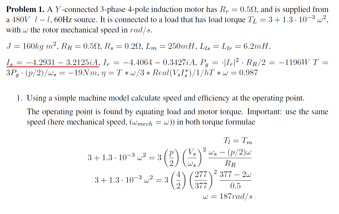
  1. My question is, how was \$ I_{stator} \$ found out?

Y -connected 3-phase 4-pole induction motor has \$ R_r = 0.5\$ Ohm , and is supplied from a 480V l - l, 60Hz source. It is connected to a load that has load torque \$ T_L = 3 + 1.3 \cdot 10^{-3} w^2 \$, with \$ w \$ the rotor mechanical speed in rad/s.

Here's full problem with data and solution with no explanations:

Problem1

I know the general idea of how asynchronous induction motor works, but I don't quite know about equivalent circuits and how everything connects to make proper calculations.

For instance, is this the equivalent circuit model for stator?

If yes, then is it simply \$V_s (\frac{480}{\sqrt(3)})\$ divided by the equivalent impedance of the whole circuit shown?

In the problem, impedances need to be re-calculated to look like \$ X_m \$ and \$ X_{ls}\$, the way it is done is by formula: \$ L_m \cdot f_{stator}\$ (in rad/s). But in my case, can I just use given 60Hz?

So \$X_m\$ would be \$L_m\$ \$\cdot f_s = 250mH \cdot (60 \cdot 2\pi) = 94.25\$ ?

  1. What's the difference between \$w_m\$ (mechanical) and \$w_r\$ (rotor speed?) in this very similar problem? I thought it meant the same thing, yet in formula for calculating \$w_s\$ (speed of stator), both of these properties are used, as if they're two different things. So what is mechanical speed then?
\$\endgroup\$

1 Answer 1

3
\$\begingroup\$

For instance, is this the equivalent circuit model for stator?

That is the equivalent model of one phase of the entire motor. The stator part consists of Rs, Xs and Xm. Wr and Rr are the rotor components. Note that it has been simplified to remove the effect of the stator:rotor turns ratio. However you can assume that the rotor parameters given are the values referred to the stator circuit. Referral to the stator means that the stator frequency can be used to calculate both Xs and Xr. The speed of the rotor is the mechanical speed.

The stator current is calculated by dividing the phase voltage by the equivalent complex impedance of the entire circuit shown.

The speed of the stator magnetic field in radians per second is 4xPixf/poles. The speed of the rotor (mechanical speed) is the speed of the stator magnetic field minus the slip. The speed of the rotor magnetic field is the same as the speed of the stator magnetic field. In the other problem, I believe that the stator omega is the frequency of the power and the mechanical speed is the speed of the magnetic field.

To further explain the concept:

Conceptually, the mechanical structure must always be kept in mind. In analyzing motor performance, "no-load" is assumed to be operation with nothing connected to the shaft. Except for that special condition the speed of the rotor = speed of load. The torque developed in the rotor = torque of load plus mechanical losses in the motor consisting of bearing friction and aerodynamic drag on the rotor (windage). In this problem, mechanical losses seem to be considered to be part of the load or considered to be negligible. Stator speed = field speed = synchronous speed.

It appears that iron losses have been considered as negligible in this problem. In the equivalent circuit, iron losses (hysteresis and eddy-current losses) would be represented as a resistor in parallel with Xm. That is a rather large loss to neglect, but I it is probably necessary to neglect it in order to construct the problem the way is is constructed.

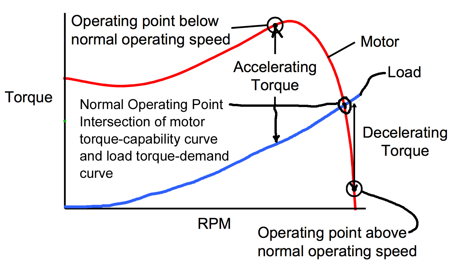
Motor & Load Torque vs Speed

This problem defines load torque demand, the torque required to drive the load at a given speed. The load torque demand is proportional to speed squared. That would be typical for a fan. Information is provided to define the motor torque capability as a function of speed. The steady-state operating speed and torque for a motor driving a load is the intersection of the motor torque capability curve and the load torque demand curve. If the actual operating speed is above or below the normal operating point as it is when the motor is initially energized, the excess motor torque capability is applied to accelerating the motor and load inertia to the normal operating speed.
enter image description here

\$\endgroup\$
6
  • \$\begingroup\$ well I still don't know how \$ I_{stator} \$ was found, is it \$V_s\$ divided by equivalent impedance? \$\endgroup\$
    – Jack
    Commented Nov 7, 2017 at 21:11
  • \$\begingroup\$ To find equivalent impedance, I need to know what's \$R_R \cdot \frac{w_0}{w_s - w_0} \$ is. What's \$w_0\$. Is it the output of whatever was loaded? So it's like output of the load? Is it gonna be equal to rotor speed? Also, if \$w_m = w_r \$ how come they're not the same in this problem: i.imgur.com/b1qrGi1.png \$\endgroup\$
    – Jack
    Commented Nov 7, 2017 at 23:21
  • \$\begingroup\$ If the several problems are not from the same source, the notation may be different. I think Wo must be synchronous speed and Ws must be slip speed, but to be sure, I would need to derive it from the form I am more familiar with, speed (n) in RPM and slip (s) as a fraction of synchronous speed. I don't seem to have the patience to sort that out right now. \$\endgroup\$
    – user80875
    Commented Nov 8, 2017 at 1:07
  • \$\begingroup\$ okay, just conceptually. Is it clear from the problem that the load also has output speed? I mean, is it always the case that the torque of load = torque of rotor? If yes, then speed of rotor = speed of load, correct? There's only one speed of stator = which is the speed of the magnetic field induced in stator by alternating currents, in rad/s (also known as synchronous speed)? \$\endgroup\$
    – Jack
    Commented Nov 8, 2017 at 4:19
  • \$\begingroup\$ To avoid extended discussion in comments, I revised my answer. Comments that have been covered can be deleted. \$\endgroup\$
    – user80875
    Commented Nov 8, 2017 at 9:47

Your Answer

By clicking “Post Your Answer”, you agree to our terms of service and acknowledge you have read our privacy policy.

Not the answer you're looking for? Browse other questions tagged or ask your own question.