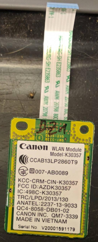
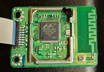
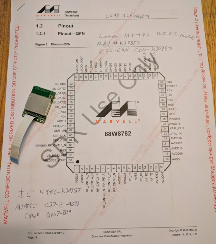
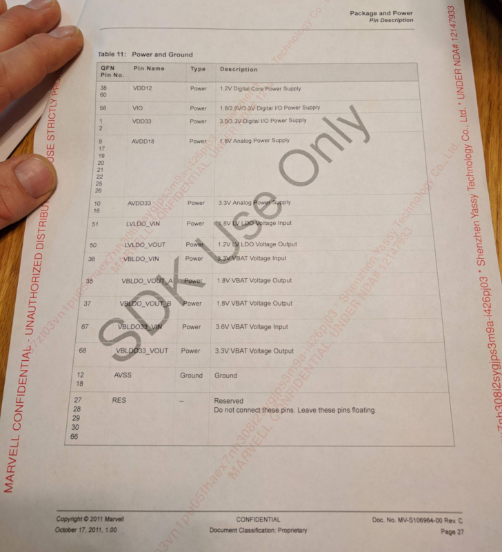
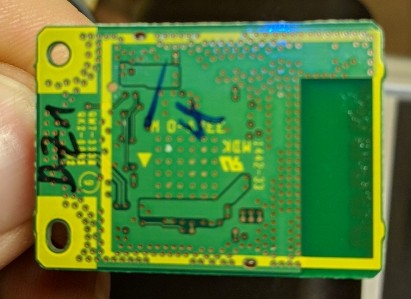
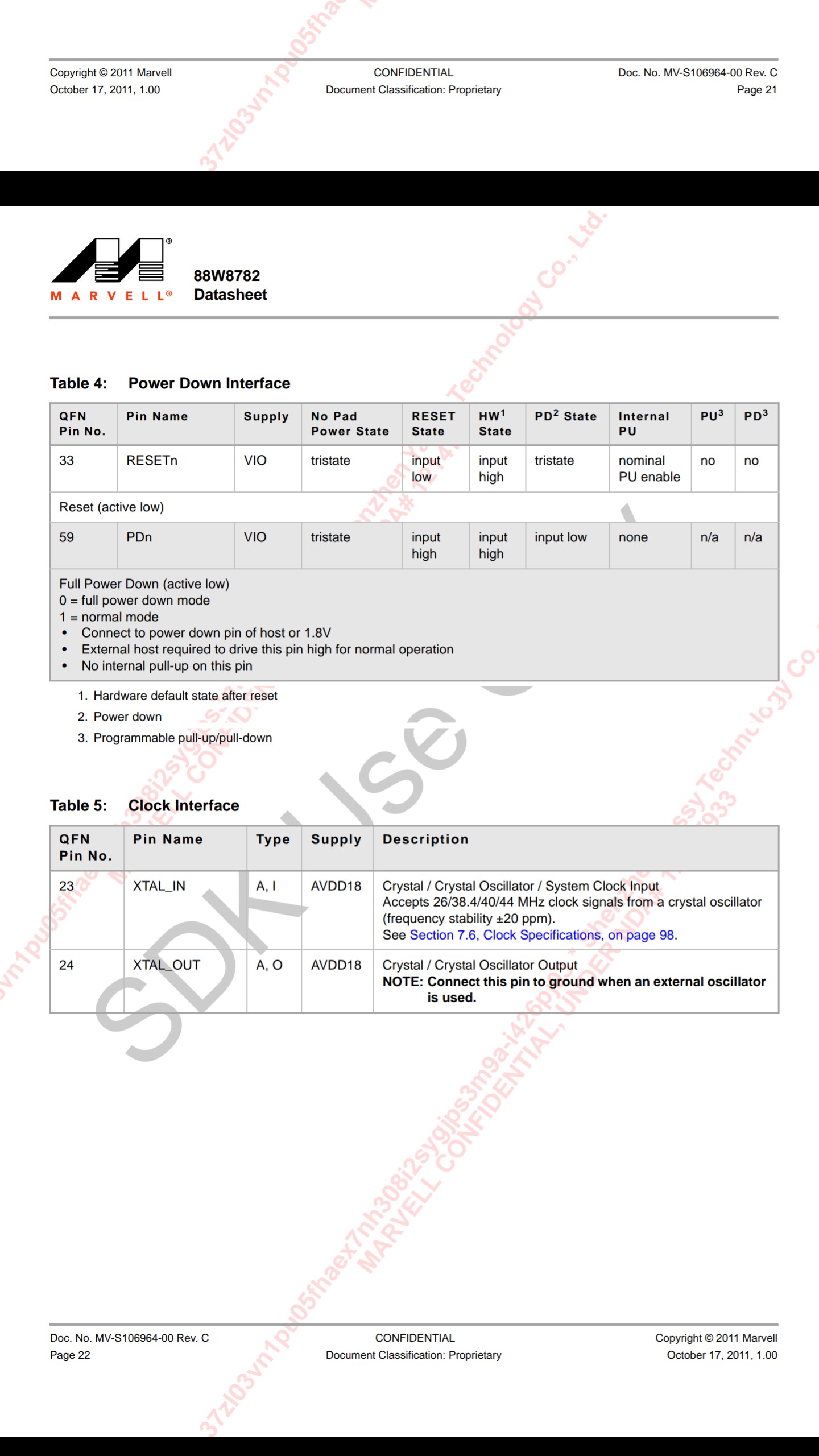
So - the pages of the datasheet you're posted don't show any USB interface pins ... but:
- this Marvell Databrief says is has a USB 2.0 interface
- this Panasonic module which uses the Marvell 88W8782 indicates that it has a USB option, and that the USB D-/D+ pins are shared with SD_CMD & SD_DAT[0] respectively.
So:
USB D+ (green) -> pin 53 (SD_DAT[0])
USB D- (white) -> pin 52 (SD_CMD)
I don't see anything on that board which looks like a regulator, and that IC appears to run on 3.3V, so you'll need a separate 3.3V regulator (because your RPi can't source enough current on the 3.3V rail) and feed it to pins 1 & 2.
Do not connect the USB 5V (red) to anything other than the input to that regulator or the smoke will come out somewhere...
You can probably hook Ground/0V (USB black) to anything connected to the shielding can.
Note that the pin numbers I'm referring are the IC pins, not the connector.
You could probably beep those through to the IC with a continuity tester.

