1
\$\begingroup\$

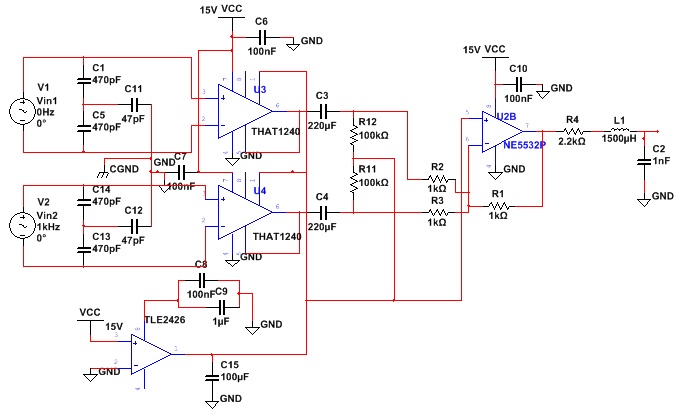
I am trying to determine the best way to ground the following audio circuit for best RF immunity. Right now I'm looking at two options, and am not sure if there's even really much of a difference between the two.

Option 1: enter image description here

Option 2: enter image description here

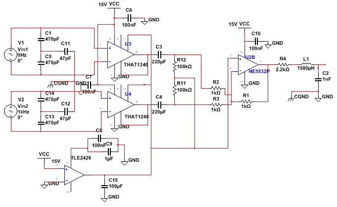
First off: I've been studying up on RFI so please correct me if I'm wrong, but as I understand it any RF pickup by the input cables (V1, V2) will most likely be common-mode, and will be shunted to earth ground through the chassis via the capacitor network (obviously assuming the interference is in the correct frequency range). The chassis is earth grounded.

In option 1, I have two chassis ground points. The caps C11 and C12 would ground to an isolated island on the pcb directly connected to the chassis. Then the signal ground would be tied at a separate location to a separate chassis ground point. I envision this as keeping the RF noise currents off of the ground plane entirely, but there is another separate chassis ground connection to the circuit. Could this possibly result in some kind of loop? I would imagine the RF current is destined for earth ground, and the shortest path is through the CGND at the input, but I'm not 100% sure if it could/would loop back.

In option 2, I've eliminated the second chassis ground connection point and tied the signal ground to the C11/C12 chassis ground point. The signal ground is still only connected to chassis ground in one place, but now there is only one connection to chassis, and the noise currents can flow through the signal ground plane to chassis ground. I would probably make a little half island or lay this out somehow to keep RF noise currents isolated to a small area while still keeping a connection between signal/chassis ground. But there would still be noise currents flowing through this interconnection.

Is either one of these options better than the other?

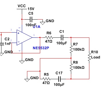
Update I've added the last half of the schematic as per Dan's response, it was left off initially only because I thought it would make the image too large for some browsers

enter image description here

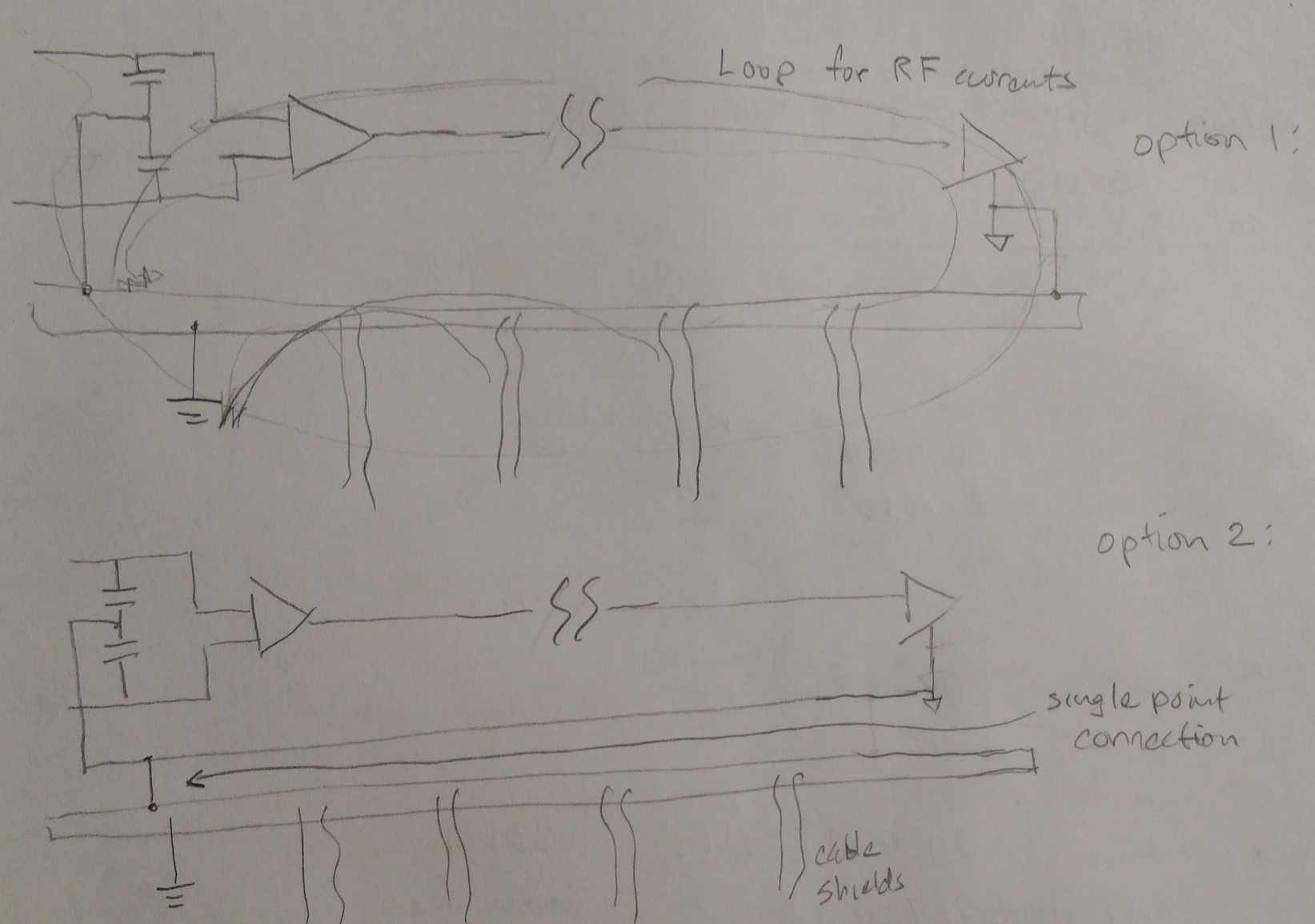
Update In regard to the comments in the discussion after DanMills's post, I am including a drawing of how I am visualizing the possible flow of shield currents and why I am having a hard time convincing myself that "option 1" is the better solution.

enter image description here

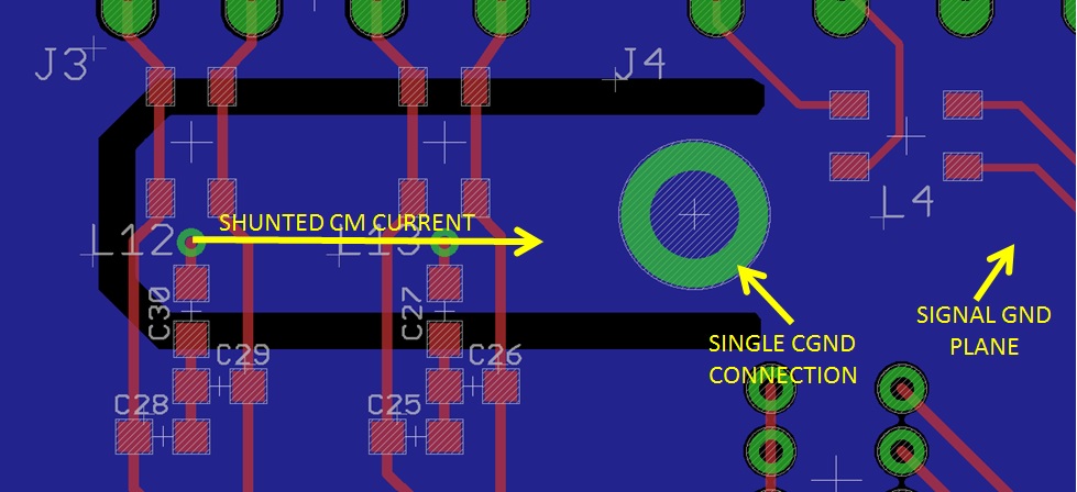
Update Here is an example of how I was thinking to lay out the board to facilitate only one chassis connection for RF noise currents, but keep them off the main ground plane.

enter image description here

\$\endgroup\$

2 Answers 2

3
\$\begingroup\$

1 gets my vote (With some modifications).

The input arrangement is just fine (Might benefit from some ferrite common mode choke, but...), and is pretty much best practise for RFI suppression on a balanced line. It adds a few hundred pF differential mode (Irrelevant at the sorts of impedances balanced lines run in pro audio) and about 45pF common mode which keep the common mode impedance usefully high in the audio and low ultrasonic while ensuring good line balance (because the 47pF cap swamps the tolerances of the 470pF caps). It does however still shunt RF to ground but you will absolutely want to minimise trace lengths in this area, small SMT C0G ceramics are good and if you use an XLR with built in pin 1 bond to chassis (You should), take advantage of it to minimise the loop area inside the box.

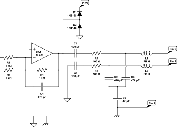
Now lets talk about the output stage.... What you have is more then a little weird, an RLC filter where the pole frequency depends upon the load impedance, and coming out single ended at that?

If you don't really need two poles here, why not lowpass with a cap across R1? then you can build out with a far more reasonable 100 ohms or so, no inductor (or a ferrite bead to help keep RF out of the doings), and you can impedance balance the output.

schematic

simulate this circuit – Schematic created using CircuitLab

C1 sets the lowpass pole, trim to taste.

The internal 0V plane needs to be connected to chassis earth at some point, but it is critical that this not share any net with the RFI or cable screen connections as doing so will create a common impedance that can couple noise into the circuit. For this reason I have shown this connection as a separate bond.

C4,C5 should be non polar and rated for at least 50V to ensure phantom power is a non problem, and D1,D2 exist to clamp any phantom power accidents (I would not suggest 4148s in practise, pick something modern in a SOT23).

L1,L2 are ferrite beads (or ideally a small ferrite common mode choke), just more measures to keep the cell phones out, and that '081 should really be a 5532 or such (Something like L1,L2 is not a bad idea at each input as well).

R4,R5 should be closely matched as they set the line balance and hence impact the CMRR of a downstream balanced receiver, 0.1% parts are not the expense they once were.

Incidentally, R1,2,3 are lower then I would prefer in a line level application, the extra current flow will tend to raise distortion at high level, a few k is more reasonable (Maybe 4k7?).

\$\endgroup\$
15
  • \$\begingroup\$ Thanks for that detailed response, sorry I should have mentioned that I left off that last half of the schematic in the interest of space. A couple things: So the LRC filter after the summer was originally a sallen-key using the left-over 5532 opamp half (I swapped it out while trying to diagnose the ground/antenna issue I've been having because I thought it might be opamp related, relatively sure now that it isn't). I also felt that the addition of another amp might add noise and the RLC filter circuit as shown would be quieter, but I can't quite confirm this, what's your take? \$\endgroup\$
    – User7251
    Commented Nov 16, 2017 at 22:25
  • \$\begingroup\$ I like the idea of adding a cap to the summer to roll-off also, I was trying to get at least a -12dB slope with cutoff around 100kHz as I felt that would help get rid of any higher frequency trash on the line. Of those 3 options, the sallen-key, the passive, or rolling off with an added cap at U2B, or any combination of the three, which do you think is preferable and why? I was thinking mostly from an added noise perspective. \$\endgroup\$
    – User7251
    Commented Nov 16, 2017 at 22:31
  • \$\begingroup\$ Re: the resistors R1/R2/R3, current measured at max signal amplitude through the 1k and out from the diff amps is just over 2mA rms (the planned output range for this is only around +12dBu or something, so not full pro-audio range due to single-ended supply). Again when sizing those I was thinking mostly about noise, the lower the better. What do you mean exactly by raise distortion at high level? \$\endgroup\$
    – User7251
    Commented Nov 16, 2017 at 22:37
  • 1
    \$\begingroup\$ At line level the contribution noise contribution from a slightly higher value resistor will be less important then the distortion contribution of a more heavily loaded opamp. I would go for a MFB (instead of a sallen and key, the MFB is better behaved at high frequency), plus a cap across R1, go for maybe 60KHz with the MFB and somewhere around 100KHz with the R1/Cap combo. You do not want to make any of this go over too low. Inductors are the least ideal of all components, avoid unless necessary. See AES48 for much on chassis and grounding. \$\endgroup\$
    – Dan Mills
    Commented Nov 16, 2017 at 23:04
  • 1
    \$\begingroup\$ For common mode ferrites, something broadly like a TDK ACM2012-201-2P-T002 (But there are dozens of variations from all the usual suspects) works well, right at the connector. \$\endgroup\$
    – Dan Mills
    Commented Nov 16, 2017 at 23:16
1
\$\begingroup\$

A single ground point is always best, so option 2 is the better of the two. The ground connection should however be as close to the inputs as possible. For audio you want to avoid ground loops like the plague. You really want one single ground plane connected back to the power supply and then connected to chassis ground there.

However, you are already using a differential receiver on the input that will reject common mode noise all on it's own. The capacitor network you have added will simply distort your input signal and shunt all your higher frequencies. For an audio system, that is a really bad idea.

Same goes for that odd filter arrangement you have on the output.

Correction: On further investigation the cap network seems to be legitimate assuming the output impedance of the source is low.

\$\endgroup\$
2
  • \$\begingroup\$ That capacitor network is actually specifically recommended on the datasheet for the THAT receiver to minimize effects on the audio while rejecting RF. Check out figure 4 here: thatcorp.com/datashts/THAT_1240-Series_Datasheet.pdf \$\endgroup\$
    – User7251
    Commented Nov 16, 2017 at 22:00
  • \$\begingroup\$ @User7251 ya thanks, I missed that, never seen it before. It is dependent on the output impedance of the source though. \$\endgroup\$
    – Trevor_G
    Commented Nov 16, 2017 at 22:01

Your Answer

By clicking “Post Your Answer”, you agree to our terms of service and acknowledge you have read our privacy policy.

Not the answer you're looking for? Browse other questions tagged or ask your own question.