9
\$\begingroup\$

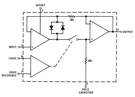
This so-called "zero drift" opamp droops .001V/sec, at temp 85C with a 1 uF cap. If I'm reading the spec correctly, that's 3.6V/hour!
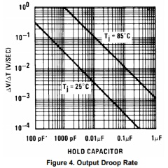
Droop Rate

http://www.ti.com/lit/ds/symlink/lf398-n.pdf

Is there a method to store a low current V for up to about 5 hours with drift or droop within my desired resolution of approx 250 ppm, or equivalent 12 bits?

"Low current" meaning mA or uA scale.

The sample rate is between once per second and once per 5 hours.

Prefer to stay in analog domain, because I want to explore and expand my analog knowledge.

The solution should be practical, and use commonly-available components

Digital solutions are ok, but should be code-free, so it's accessible to non coders, and not require a computer to implement, so it's accessible to people who don't own a computer (such as the economically-disadvantaged teens i mentor).

Not asking for specific part numbers, just the basic method.

update:
The manufacturer confirmed that my estimate droop-per-hour is correct. According to the manufacturer, droop is largely influenced by the input bias current of the buffer amplifier and whatever leakage may occur through the switch - not just normal capacitor leakage. https://e2e.ti.com/support/amplifiers/precision_amplifiers/f/14/p/641041/2365384#2365384

enter image description here

\$\endgroup\$
16
  • 10
    \$\begingroup\$ If ADC is an option, digitize your data and store it on a flash chip for years. \$\endgroup\$ Commented Nov 20, 2017 at 8:25
  • 2
    \$\begingroup\$ @JohnyRadio summarizing other users' suggestions, perhaps storing the analog value of the signal is not the smartest thing to do, it doesn't mean it can't be done. But the reason for the remarks is that putting constraints without stating a reason pass off like a way to get people to acknowledge what you have in mind. Not that it's that the case, but try to motivate your constraints. \$\endgroup\$
    – clabacchio
    Commented Nov 20, 2017 at 14:13
  • 3
    \$\begingroup\$ What is this for? I don't think it's possible in pure analog unless you go full Heath Robinson and include things like motorized faders (expensive) or build your own memory (time consuming, not scalable) \$\endgroup\$
    – pjc50
    Commented Nov 20, 2017 at 14:22
  • 4
    \$\begingroup\$ 1.) That's not (just) an opamp. 2.) The droop is from the capacitor discharging. The capacitor will discharge by itself - they have a leakage current, and with enough time will completely discharge. The opamp in that chip must also draw a (tiny) bit of current from the hold capacitor - this will also discharge the capacitor over time. This chip is not intended for what you are trying to do. It is also older than dirt. It recommends using an LM3905 at one point. Those were old when I was a kid back in the early 1980s. \$\endgroup\$
    – JRE
    Commented Nov 20, 2017 at 15:51
  • 3
    \$\begingroup\$ What problem are you exactly trying to solve? It look's like XY problem. \$\endgroup\$ Commented Nov 21, 2017 at 10:35

7 Answers 7

23
\$\begingroup\$

Well, there seem to be solutions, although it's a bit of a blast from the past...

A Survey of Analog Memory Devices (from 1962) says:

The transpolarizer, an electrostatic analog of the more widely known transfluxor [...]

For a more modern solution, a micro with ADC and DAC seems the way to go. Also, unlike the analog solutions, it is much more likely to be stable with temperature, which is always a nice bonus.

Regarding large capacitors, there are several problems:

  • Capacitor value depends on temperature, thus with a constant amount of charge in your capacitor, the voltage will vary with temperature. The effect will be tiny, or huge, depending on capacitor type.

  • Capacitor leakage depends a lot on temperature (for electrolytic ones).

  • X7R is a piezoelectric microphone.

  • Dielectric absorption (DA) means that you charge your capacitor, then disconnect it, wait a bit, and then the voltage on it is now different! And it depends on the voltage that was there before you charged (or discharged it). Also, for large capacitors intended for supply decoupling, the effect is absolutely harmless, so no-one cares about it, and therefore there is no specification. I don't know if it depends on temperature and aging, but there is no reason why it would not. You will only get a useful specification for capacitors that are intended for high precision integrators and stuff like that.

I remember measuring leakage on a 470µF 6V3 Panasonic FR capacitor. I charged it to 5V for a few minutes, then measured it every few minutes. The voltage would drop quickly due to DA, then it stabilized at around 4V. I left the capacitor on a shelf for a week, and measured again. Calculated leakage was in the nanoamps, but you'd have to keep it at the target voltage for a while (like at least several hours, if not days) in order to overcome dielectric absorption, so it would be completely useless in this application.

\$\endgroup\$
12
  • 2
    \$\begingroup\$ Upvoted for "transfluxor" :) \$\endgroup\$
    – pjc50
    Commented Nov 20, 2017 at 16:42
  • 1
    \$\begingroup\$ For low DA and low leakage, you need film caps, and then a low drift opamp... it will still drift though. electronics.stackexchange.com/questions/39586/… \$\endgroup\$
    – bobflux
    Commented Nov 20, 2017 at 16:59
  • 2
    \$\begingroup\$ i appreciate the info in this answer, but i'm confused by all the upvotes-- it does not seem to contain an analog solution. \$\endgroup\$ Commented Nov 20, 2017 at 22:09
  • 1
    \$\begingroup\$ This answer seems to get most votes for the fun photo. There are practical solutions getting pushed down by this answer due to a fun photo. \$\endgroup\$ Commented Nov 22, 2017 at 12:57
  • 1
    \$\begingroup\$ @JohnyRadio - Photo removed. \$\endgroup\$
    – SamGibson
    Commented Aug 5, 2021 at 18:27
19
\$\begingroup\$

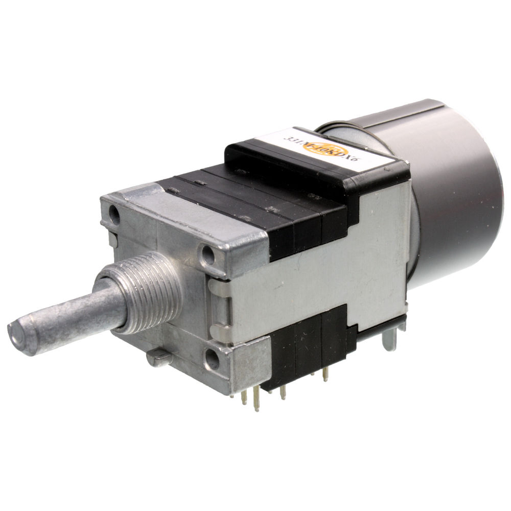
Get a motorized potentiometer. motorized potentiometer To sample use an opamp to drive the difference to zero, to hold don't move it. Accuracy will probably be pretty low, but hey no drift.

\$\endgroup\$
5
  • \$\begingroup\$ Great idea, tho worried about precision as well as mechanical wear. \$\endgroup\$ Commented Nov 20, 2017 at 16:44
  • 1
    \$\begingroup\$ Great sizing... \$\endgroup\$
    – A.K.
    Commented Nov 21, 2017 at 2:08
  • \$\begingroup\$ What if you'd split up the signal to multiple potentiometers for improved accuracy? Oh, right, it would get so ludicrously complex you should use an ADC instead. \$\endgroup\$
    – Mast
    Commented Nov 21, 2017 at 12:51
  • \$\begingroup\$ @Mast: multiple potentiometers connected in gearbox with a single motor? That would work. \$\endgroup\$
    – A.K.
    Commented Nov 21, 2017 at 15:42
  • \$\begingroup\$ @Mast seems a single pot could achieve desired precision. \$\endgroup\$ Commented Nov 22, 2017 at 12:51
12
\$\begingroup\$

While much easier in digital, you can certainly do this in analog with some careful part selection.

Essentially, you need three high performance components:

  • A low leakage capacitor
  • A low leakage analog switch
  • A low input bias current op-amp for your output buffer

Forget about conventional ceramic capacitors if you plan to hold for hours. Your best bet is a polypropylene film capacitor. Bob Pease wrote a great article about characterizing their leakage rate: What's all this capacitor leakage stuff, anyhow? It's on the order of millivolts per day, which is probably sufficient for your application.

The switch is an oft-overlooked part of this. You'll find that even the best off-the-shelf solid state analog switches have leakages in the range of a few picoamps. A 10 pA leak rate means that for a 1uF cap, you'll drain off 180mV over a five hour period. This may or may not be acceptable to you. If you need to do better, a better solution is a reed relay, which has essentially negligible leakage due to the fact it actually puts an air gap between contacts.

In terms of low input bias current opamps, there are quite a few options available. I recently used the LMP7721 from TI on a high-impedance design. It's got a maximum Ib of 20 fA at room temperature and 900 fA at 85°C.

So, we can pretty easily imagine a design which incorporates a polypropylene cap, a reed relay, and a low Ib buffer. Let's imagine that we use:

With the above components at room temperature, you'd have the following error contributions after 5 hours:

  • A 4.5% droop from the RC time constant of the cap.
  • Essentially negligible drift from the reed relay
  • Essentially negligible drift from the buffer.

This is assuming you have a proper low-impedance layout (eg: removed soldermask from the board, use a driven guard ring).

Also, the RC value for the polypropylene cap is a worst-case value: the real world is probably better. Correction: that's a typical value. However, as Pease found in the article linked above, a polypropylene cap after soaking can have a time constant on the order of years. This will therefore require some experimentation and probably binning.

So, it's certainly possible to do this in analog, although probably not practical when the alternative is to digitize the output.

\$\endgroup\$
10
  • \$\begingroup\$ I don't know where you got that RC time constant of 40000 s from. The datasheet says >5000 s. Film capacitor manufacturers seem to avoid rating anything to a higher insulation resistance than 5000 megaohm-microfarads (seconds). Here's a 0.47uF, 63V film cap with the same rating: digikey.com/product-detail/en/kemet/RSBDC3470AA10J/399-6045-ND/… \$\endgroup\$
    – τεκ
    Commented Nov 21, 2017 at 18:03
  • 1
    \$\begingroup\$ Page 11 of the datasheet has an RC vs. temperature curve: imgur.com/eHQjXej. Generally, manufacturers will be loathe to guarantee extremely high insulation resistance even if the cap can do it. As Pease found in the linked article, a polypropylene cap at room temperature after soaking can have an RC time constant on the order of ten years. That, of course, will be with the leads in air (since board surface leakage will dwarf that), and certainly can't be guaranteed with every cap that comes off the line. \$\endgroup\$ Commented Nov 21, 2017 at 18:16
  • \$\begingroup\$ You're right though, that curve isn't a worst-case value, it's a typical. I've updated my answer accordingly. \$\endgroup\$ Commented Nov 21, 2017 at 18:25
  • \$\begingroup\$ I found some others that have higher rated insulation resistance up to 30000 seconds, but definitely agree that real world results are much better. \$\endgroup\$
    – τεκ
    Commented Nov 21, 2017 at 18:34
  • \$\begingroup\$ Also somewhat relevant, another Bob Pease article about femtoampere current measurement test setups: electronicdesign.com/test-amp-measurement/… \$\endgroup\$ Commented Nov 21, 2017 at 19:46
10
\$\begingroup\$

With standard analog components the answer to this would be no, not really.

Of course, with big enough capacitors or other storage elements, you could maintain the level to within a desired differential over a long period, but there will always be some loss over time. Further, the act of extracting information from the storage device removes energy from that device.

Theoretically, with a super-conductive loop, suitably isolated from any external magnetic fields, you could establish an indefinite current. But again, measuring that current would involve energy removal.

ADDITION

Another alternative might be to "permanently" magnetize some material or substance in the presence of a hall-effect sensor. With the right material, you could store that "level" for a very long time.

But, of course, it would be a lot cheaper and easier just to do it digitally.

However, you do not need a micro.

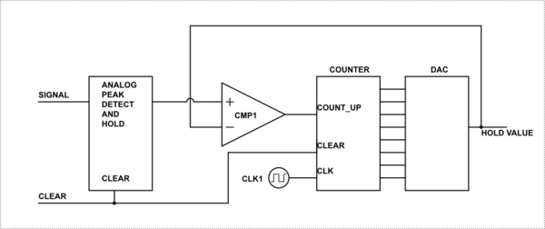
The following is a hybrid analog/digital Peak Detect and Hold circuit.

schematic

simulate this circuit – Schematic created using CircuitLab

The circuit uses a follower DAC to slew a voltage level from a counter to match the voltage on the capacitor. Once the DAC value is matched the count stops and the output voltage will be maintained as long as the power is on, or until the CLEAR signal is sent. The cap now only needs to hold the peak level for however long it takes the counter to ramp up to that voltage. Obviously, granularity of the output depends on the number of bits in the counter/DAC.

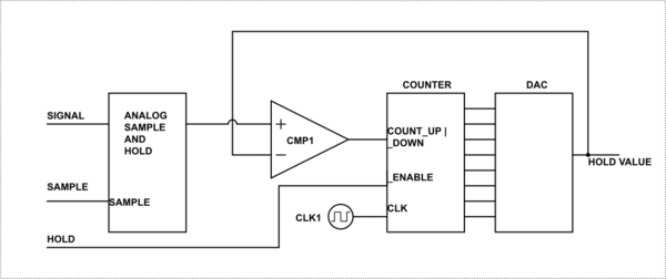
A true "Sample and Hold" circuit would require an extra input as shown below, or some form of window comparator to detect when the counter is within a step of the value.

schematic

simulate this circuit

If the slew rate of the counter/DAC is faster than the slew rate of your original signal, you do not need the analog sampler at all.

\$\endgroup\$
13
  • 1
    \$\begingroup\$ @JohnyRadio see first sentence. \$\endgroup\$
    – Trevor_G
    Commented Nov 20, 2017 at 22:41
  • 1
    \$\begingroup\$ @JohnyRadio perhaps, but then again, you didn't ask a specific question with specific requirements. \$\endgroup\$
    – Trevor_G
    Commented Nov 21, 2017 at 1:13
  • 1
    \$\begingroup\$ @JohnyRadio anyhow, I updated my answer with to show you a hybrid analog/digital way to do it. \$\endgroup\$
    – Trevor_G
    Commented Nov 21, 2017 at 1:41
  • 1
    \$\begingroup\$ @JohnyRadio Sample is the digital signal that makes the S&H hold the current analog level. I was not sure from your original question if you were talking about a true S&H or a Peak Detector, so I added both. the circuit shown is a block diagram, what you put in the blocks is up to you. \$\endgroup\$
    – Trevor_G
    Commented Nov 22, 2017 at 13:00
  • 1
    \$\begingroup\$ @JohnyRadio yes you can probably find the whole thing in a single chip. The counter/DAC I mean. \$\endgroup\$
    – Trevor_G
    Commented Nov 22, 2017 at 13:53
7
\$\begingroup\$

I’ve seen this done with a reed relay, an AD545 op-amp (there are better ones now), and a large 100 volt polypropylene capacitor. The board maker can make cuts on the board that work better than guard rings alone. The relay was NOT an epoxy molded type but an "open frame" type of some sort. The op-amp was in a can, but that will not be possible these days.

This rig was stable for days.

\$\endgroup\$
2
  • 1
    \$\begingroup\$ THIS. Very interesting, but i need to understand more. So, the V of the cap, rather than it's value, is they key? Yes, i have read that polyprops exhibit the least droop of all cap types-- seems that's the secret sauce here. I don't see how the switch would impact droop, since that's on the input-- there's cap leakage on the input? Many thx. \$\endgroup\$ Commented Nov 20, 2017 at 22:39
  • 1
    \$\begingroup\$ The 100 volts is part of the key. The size I don't remember, but it was large. An early version used polyester but PP was better. Teflon might be better but not by much. A solid state switch has leakage, although you can get better ones now. This design dates from the days before micros. \$\endgroup\$ Commented Nov 20, 2017 at 23:18
1
\$\begingroup\$

Lets first analyze whether it is reasonable to store a 12-bit sample for 5 hours with a capacitor.

A capacitor will self discharge according to the following equation.

V = V_0 * e^(-t/(R*C))

V is the capacitor voltage.
V_0 is the initial voltage at t = 0.
t is the time in seconds.
R is the insulation resistance of the capacitor.
C is the capacitor value.

Capacitors in a particular series/technology are often rated as having an R*C constant in mega-ohms * micro-farads.

To achieve less than 1 LSB of droop on an N-bit measurement over a timespan of T seconds you would need...

V / V_0 = (1 - 1/2^N)

, which implies that

R*C >= -T/ln(1 - 1/2^N)

If we let N be 12 bits, and T = 18000s (5 hours) that makes the insulation resistance * capacitance time constant to be R*C = 7.37E7 seconds, which is 2.34 years.

Polypropylene film capacitors are one of the lowest leakage types available on the market. Lets take the Vishay BFC233827105 as an example (this capacitor series was mentioned Synchrondyne's answer). It is 1uF and has an R*C product 200,000s seconds. Based on the above calculation, this is like 368 times shorter than what would be required to meet your specification.

https://www.vishay.com/docs/28119/mkp3382x2.pdf

So basically there is no hope of storing a voltage with 12-bit accuracy for 5 hours with any commercially available capacitor, because the requirement is 100s of times more strict than what's available on the market. Once you attach sample and hold switches and op-amps to the capacitor, the problem only gets worse due to the additional leakage paths.

If we relax the requirement to 10-bits resolution for like 3 minutes then we have a chance.

You are going to have to store the value digitally if you want to meet your spec.

\$\endgroup\$
1
  • \$\begingroup\$ please correct spelling mistakes: - weather -> whether, Megaohms -> megohms, file -> film. \$\endgroup\$ Commented Aug 5, 2021 at 21:32
-2
\$\begingroup\$

Solution 1

If you know the leakage slope of your cap, you could repeatedly "top off" the cap at timed intervals, to compensate for droop.

However, the slope is likely nonlinear, so the top-off amount would be nonlinear. It's possible the amount could be a simple percentage of the cap's charge level, which would simplify things.


Solution 2

If you have access to chip fabrication facility, you may be able to replicate this esoteric "3-transistor nonvolatile analog storage cell with 14 bits effective resolution it consists of charge stored on a MOS transistor floating gate, is written by means of hot-electron injection and erased by means of gate oxide tunneling. Small size and low power consumption."

https://pdfs.semanticscholar.org/ed68/f94ad3d4bfad1126e83d152e23e6e6e0e495.pdf

Or this technique, using EEPROM as an analog storage device:

https://people.eecs.berkeley.edu/~hu/PUBLICATIONS/Hu_papers/Hu_JNL/HuC_JNL_194.pdf


Solution 3

Tho not analog, you could use a dedicated ADC chip straight to a latch. That could avoid using an MCU, which keeps the solution code-free, per the OP.

You may have to use various discrete logic chips, clocks, or counters, to get the latching to work.

This Maxim chip, for example, is said to work without a MCU (not a product endorsement).

https://www.maximintegrated.com/en/app-notes/index.mvp/id/1041

Here's another example of using an ADC without an MCU.This system is far more complex than what the OP needs. For example, as an audio recorder, it's sample-rate and storage requirements far exceed the OP's needs.

http://ultimationee.blogspot.com/2011/09/digitally-recording-and-playing-back.html


Solution 4

You may use commonly available, inexpensive digital potentiometers. They are available with persistent storage, and are simple to use.

However, their resolution is not very high, ranging from 100 to 256 steps. You could use 5 in series to achieve effective 12 bits of resolution.

Could be driven directly from an ADC on the input, avoiding an MCU. So basically you'd be using these as a latch. A latch might be easier.

This link is not intended as an endorsement of any product or distributor

https://www.mouser.com/Mobile/Semiconductors/Digital-Potentiometer-ICs/_/N-4c498/

\$\endgroup\$
1
  • \$\begingroup\$ Comments are not for extended discussion; this conversation has been moved to chat. \$\endgroup\$
    – clabacchio
    Commented Nov 22, 2017 at 13:08

Your Answer

By clicking “Post Your Answer”, you agree to our terms of service and acknowledge you have read our privacy policy.

Not the answer you're looking for? Browse other questions tagged or ask your own question.